Apparatus and method of controlling same
- Summary
- Abstract
- Description
- Claims
- Application Information
AI Technical Summary
Benefits of technology
Problems solved by technology
Method used
Image

Examples
first embodiment
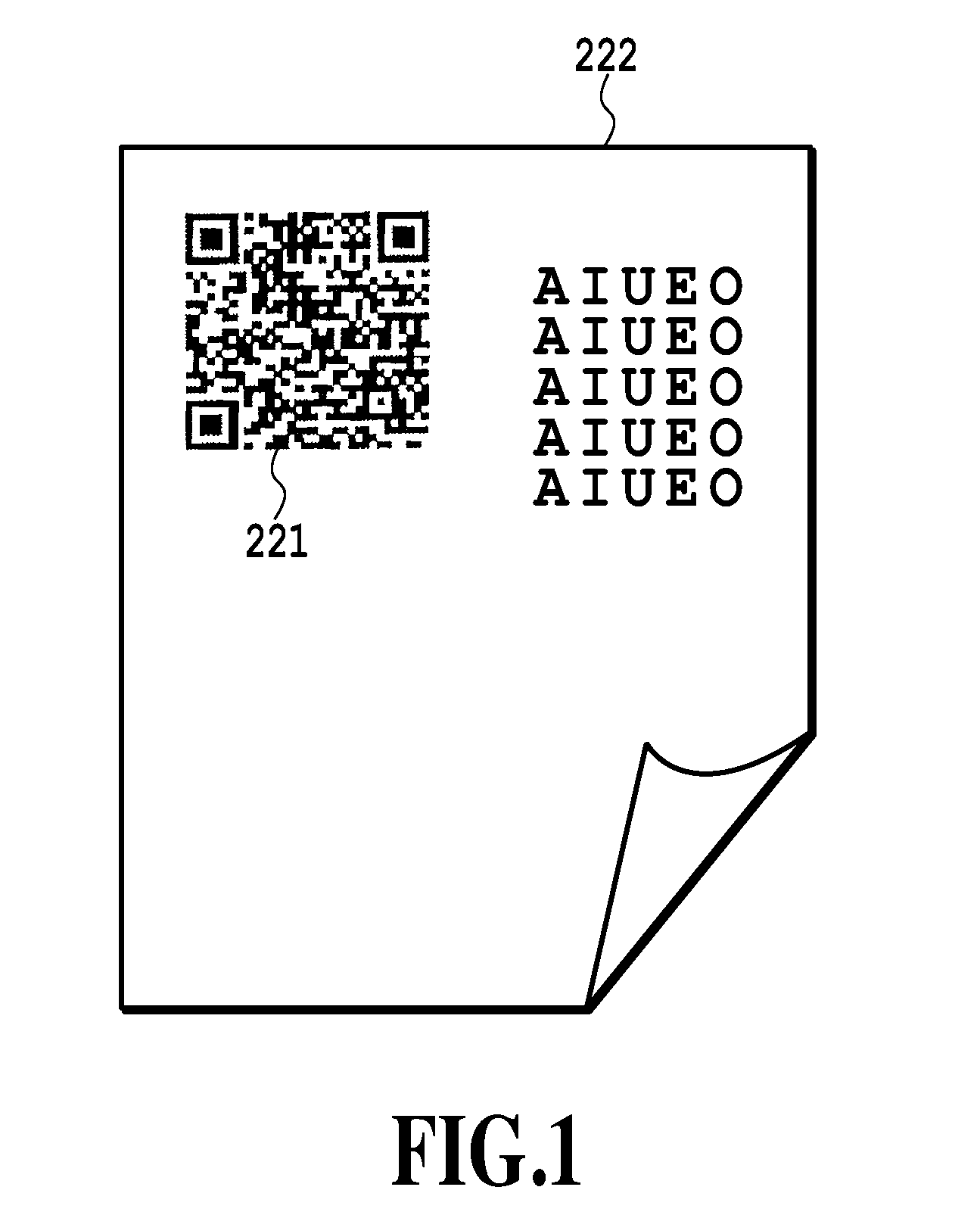
[0029]FIG. 1 is a diagram showing an outside appearance of a piece of printed matter containing a bar code. In FIG. 1, a bar code 221 is printed on a top left side of a piece of printed matter 222. Here, a position where the bar code 221 is printed, or a size and number of the bar code 221 are arbitrarily provided. In addition, in the figures used for explanation of the present invention, an example of the bar code is shown as a QR code (registered trademark), but the bar code may be any code other than the QR code (registered trademark).
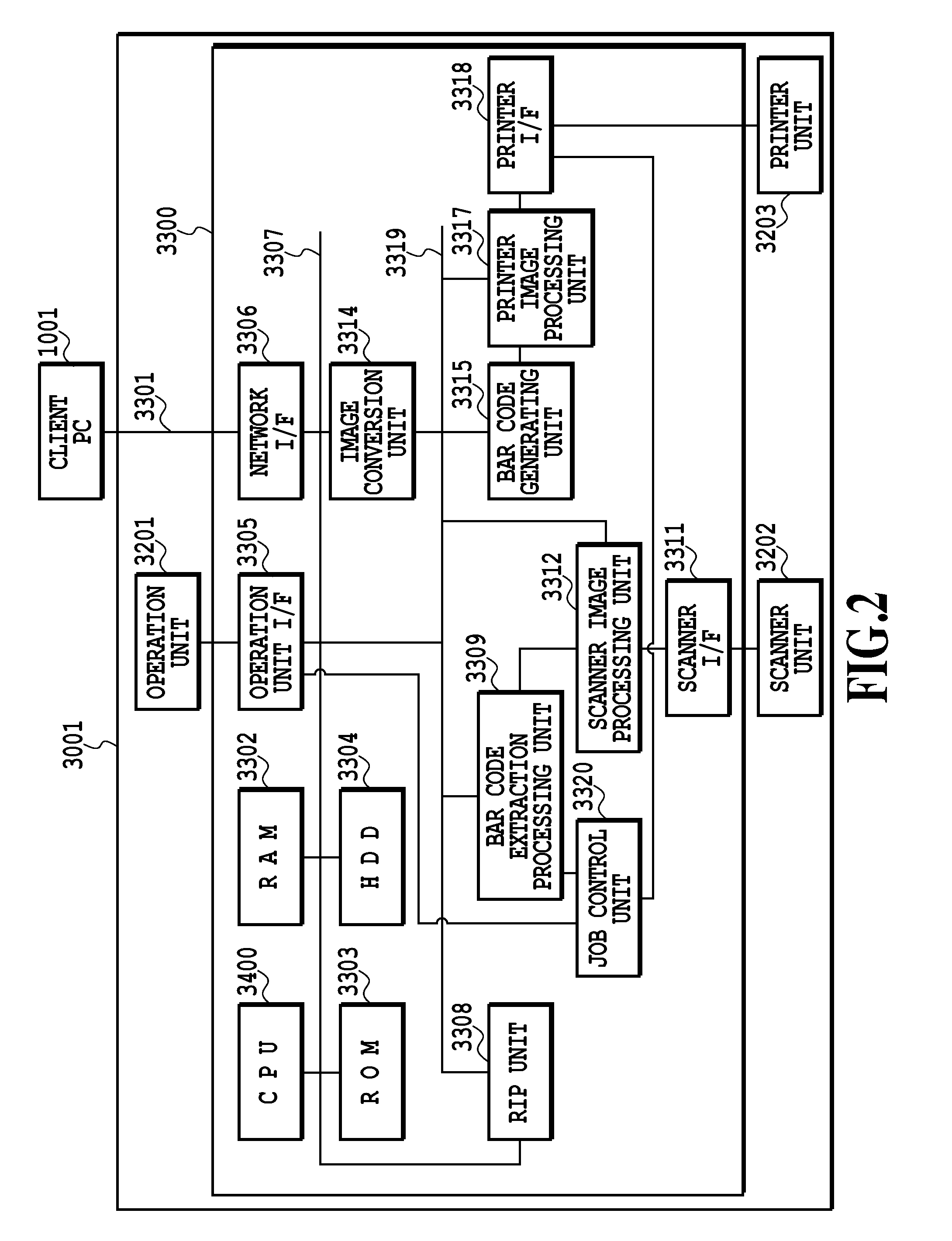
[0030]FIG. 2 is a block diagram showing an inside of an image processing apparatus 3001.
[0031]A controller 3300 controls a scanner unit 3202 and a printer unit 3203. In addition, the controller 3000 controls data communications between a client PC 1001 and an image processing apparatus 3001 through a LAN or WAN 3301.
[0032]A RAM 3302 is a work memory for operating a CPU 3400, and is also a memory for temporarily storing manuscript image data which th...
second embodiment
[0126]Next, a second embodiment will be explained.
[0127]FIG. 8A is a diagram showing a reading range of a paper manuscript and a detection range of a bar code in the scanner unit 3202.
[0128]The maximum manuscript reading range 801 is the maximum reading range of the scanner unit 3202.
[0129]The manuscript reading range 802 is an area for scanning a sheet placed on a manuscript table and is a range set to be matched to a size of a paper manuscript at the time the paper manuscript is actually read within the maximum manuscript reading range 801. Accordingly, data scanned in the manuscript reading range 802 are manuscript image data. It should be noted that the manuscript reading range 802 becomes equal to the maximum manuscript reading range 801 at a maximum and does not expand any larger than it without mentioning.
[0130]The bar code detection ranges 803 to 806 are a region in advance set within the manuscript reading range 802 and are a search area in which the processing for searchin...
third embodiment
[0166]Next, a third embodiment will be explained. In the second embodiment, in a case where it is determined that the bar code is embedded out of the prescribed areas 811 to 814 in the manuscript image data, the bar code in the manuscript image data is deleted. In addition, there are produced the print image data in which the new bar code is added in the prescribed area set by a user.
[0167]The third embodiment can, in a case where it is determined that the bar code is embedded out of the prescribed areas 811 to 814 in the manuscript image data in the same way with the second embodiment, prevent the event that pieces of the original bar code are left on the copied object or the original bar code and the new bar code both exist.
[0168]FIG. 9 is a flow chart showing the process order of copy control performed by the copying machine.
[0169]At step S9001, the operation unit 3201 receives a copy start instruction from a user. When the instruction is conveyed to the scanner unit 3202, the sc...
PUM
 Abstract
Description
Claims
Application Information
 - Generate Ideas
- Intellectual Property
- Life Sciences
- Materials
- Tech Scout
- Unparalleled Data Quality
- Higher Quality Content
- 60% Fewer Hallucinations
Browse by: Latest US Patents, China's latest patents, Technical Efficacy Thesaurus, Application Domain, Technology Topic, Popular Technical Reports.
© 2025 PatSnap. All rights reserved.Legal|Privacy policy|Modern Slavery Act Transparency Statement|Sitemap|About US| Contact US: help@patsnap.com