Side lighting optical fiber

a technology of optical fibers and side lights, applied in the field of side lighting optical fibers, can solve the problems of impairment of the external appearance of the fiber, etc., and achieve the effect of good external appearance and characteristics

Inactive Publication Date: 2011-03-17
3M INNOVATIVE PROPERTIES CO
View PDF24 Cites 33 Cited by
  • Summary
  • Abstract
  • Description
  • Claims
  • Application Information

AI Technical Summary

Benefits of technology

[0006]In one aspect the present disclose provides a side lighting optical fiber comprising a core containing a first light scattering agent, and a clad disposed generally concentric to the core and containing a second light scattering agent, wherein light transmittance of the clad at a wavelength of 550 nm is in a range from 70% to 90%. Typically, even if there is layer separation at the core / clad interface or scratch on the clad surface, these defects do not become conspicuous and good external appearance and characteristics can be obtained.
[0007]Typically, side lighting optical fibers described herein exhibits good external appearance and characteristics which are not significantly affected by possible layer separation at the core / clad interface or possible scratch on the clad surface.

Problems solved by technology

However, when titanium oxide is added to the clad as in the optical fiber, if separation of layers occurs at the core / clad interface due to shock or the like, light scattering is reduced at the separated region, which gives rise to the appearance of so-called “dark defect”, leading to impairment of the external appearance of the fiber.
However, with this optical fiber, since the clad is free of light scattering agent and is transparent, if scratch is produced on the clad surface, the scratch may strongly scatter light, giving rise to so-called “bright spot”, which again leads to impairment of the external appearance of the fiber.

Method used


Image

  • Side lighting optical fiber
  • Side lighting optical fiber
  • Side lighting optical fiber

Examples


example 1

1. Preparation of the Clad

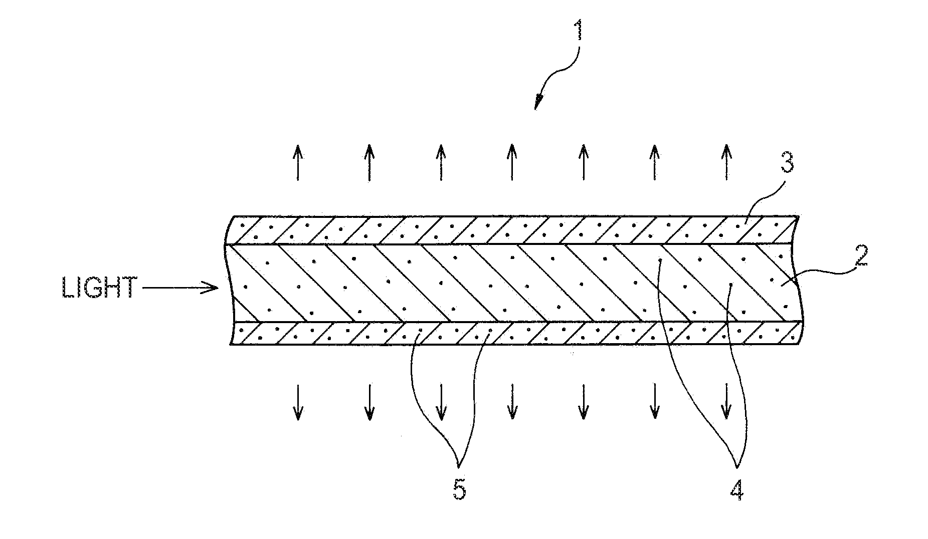
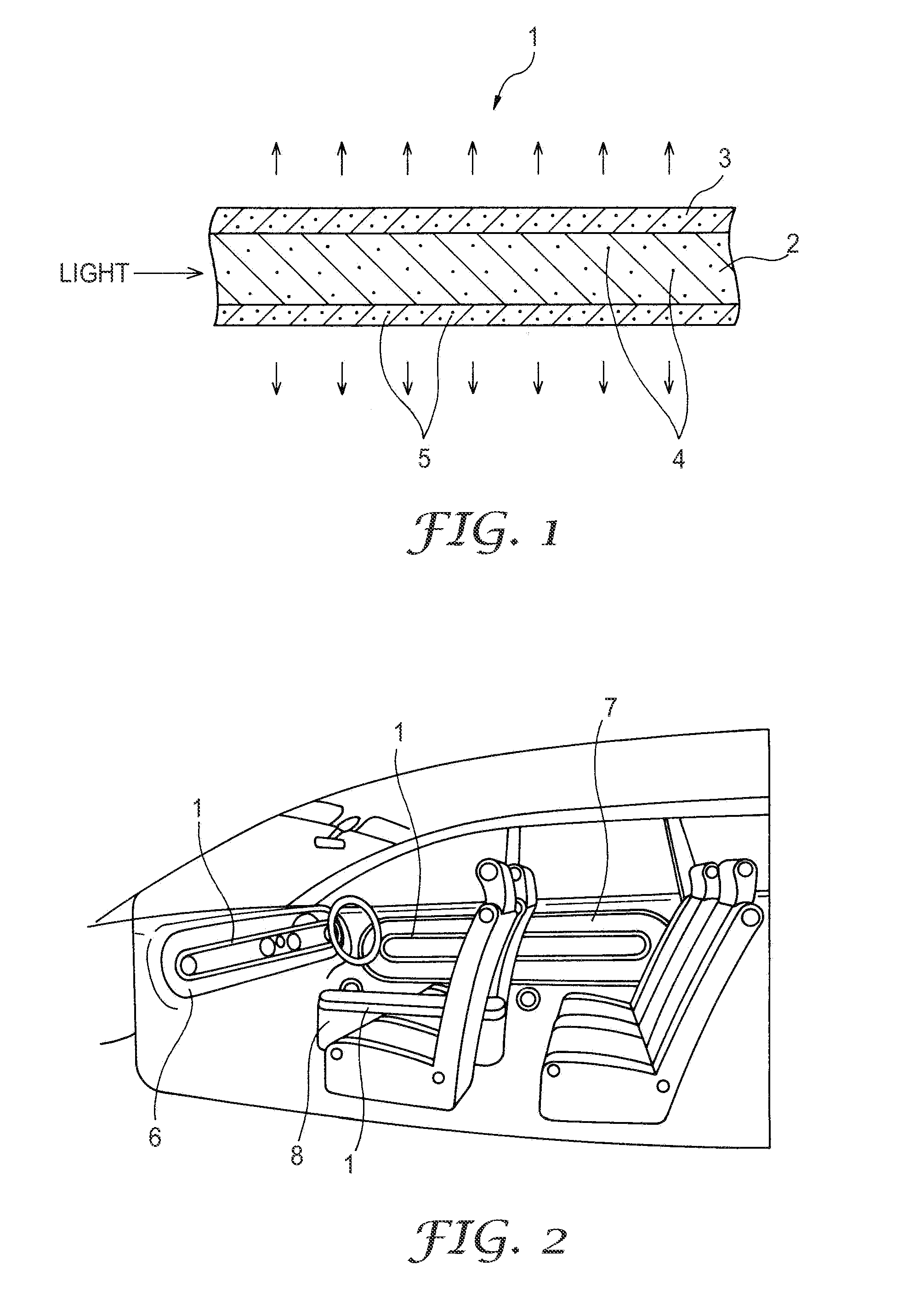
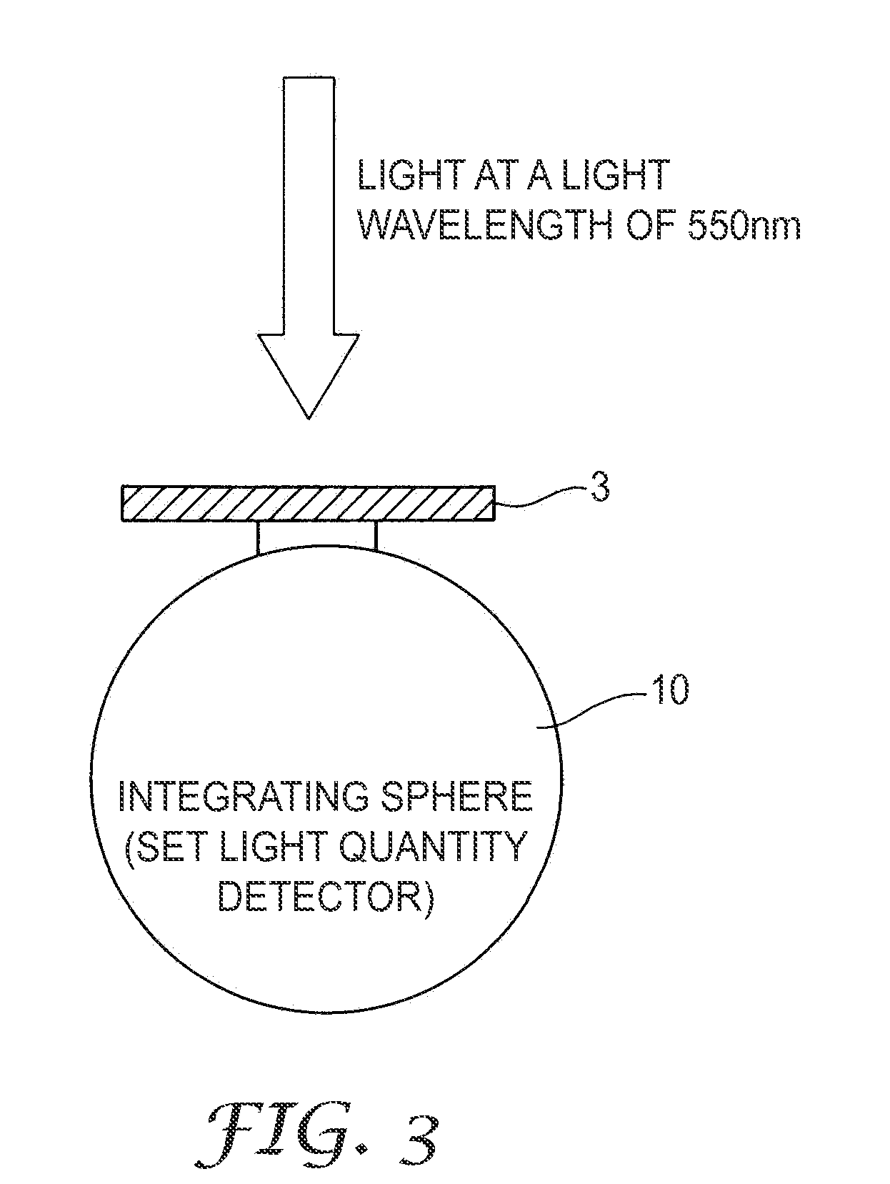
[0026]100 parts by mass of tetrafluoroethylene hexafluoropropylene copolymer (FEP) (obtained under the trade designation “FEP-100J” from Du Pont Mitsui Fluoro chemicals Co., Tokyo, Japan), and 1 part by mass of FEP resin dispersed with 10% by mass of zinc oxide (obtained under the trade designation “FCMSM1109-White (D)” from Dainichiseika Color & Chemicals Co., Tokyo, Japan, were placed in a can and were mixed for 1 minute by hand shaking. The resulting mixture was extruded using an extruder with the mold heated to about 395° C. at speed of about 3 mm / minutes, and the extruded molding was cooled with water. Tubular clad of 3.25 mm in outer diameter and 0.25 mm in thickness was thus obtained. About 0.099% by mass of zinc oxide was contained in this clad as light scattering agent 5. The clad thus prepared had light transmittance of 80% at light wavelength of 550 nm. Method of measuring light transmittance is described below.

2. Preparation of the Core

[0027]Cor...

example 2

[0029]75 parts by mass of FEP (“FEP-100J”) and 1 part by mass of FEP resin dispersed with 10% by mass of zinc oxide (“FCMSM1109-White (D)”) were mixed, and was formed into a tube of 3.25 mm in outer diameter and 0.25 mm in thickness. With this, about 0.132% by mass zinc oxide was contained in this clad as light scattering agent 5. Resulting clad 3 had light transmittance of 72% at light wavelength of 550 nm. Core 2 was prepared as described for Example 1 to provide side lighting optical fiber 1.

example 3

[0030]150 parts by mass FEP (“FEP-100J”) and 1 part mass FEP resin dispersed with 10% by mass of zinc oxide (“FCMSM1109-White (D)”) were mixed, and formed into a tube of 3.25 mm in outer diameter and 0.25 mm in thickness. With this, about 0.066% by mass of zinc oxide was contained in the clad as light scattering agent 5. Clad 3 thus prepared had light transmittance of 83% at light wavelength of 550 nm. Core 2 was prepared as described for Example 1 to provide side lighting optical fiber 1.


PUM


Abstract

A side lighting optical fiber 1 having a core 2 containing a first light scattering agent 4, and a clad disposed generally concentric to the core and containing a second light scattering agent 5, such that light transmittance of the clad 3 at wave-length of 550 nm is in the range of 70-90%.

Description

FIELD OF THE INVENTION[0001]The present invention relates to a side lighting optical fiber that is applicable, for example, as auxiliary side illumination for a vehicle, a building and the like.BACKGROUND ART[0002]As an approach for increasing the side lighting brightness of a non-directional side lighting type plastic optical fiber, a method has been known in which the side lighting brightness and the decay rate of side lighting brightness is controlled by adding a minute amount of titanium oxide to the clad and varying the content of titanium oxide (see, e.g., Japanese Patent No. 3384396, published on Mar. 10, 2003).[0003]As another approach for increasing the side lighting brightness of a non-directional side lighting type plastic optical fiber, a method has been known in which the side lighting brightness is controlled by adding light scattering agent to the core and varying the content of light scattering agent (see, e.g., Japanese Patent Publication No. 2000-131529, published ...

Claims


Application Information

Patent Timeline
Patent Type & Authority Applications(United States)
IPC IPC(8): G09F13/02G02B6/02G02B6/00
CPCG02B6/001B60Q3/004B60Q3/64
Inventor IRIE, SHINICHI
Owner 3M INNOVATIVE PROPERTIES CO
Why Eureka
Try Eureka