Thermoelectric-based power generation systems and methods

a technology of power generation system and thermoelectric device, which is applied in the direction of lighting and heating apparatus, process and machine control, instruments, etc., can solve the problems of increasing the amount of waste heat, increasing the heat exhaust, and not meeting the commercial success of thermoelectric generators (tegs)

Inactive Publication Date: 2011-03-24
GENTHERM INC
View PDF82 Cites 106 Cited by
  • Summary
  • Abstract
  • Description
  • Claims
  • Application Information

AI Technical Summary

Benefits of technology

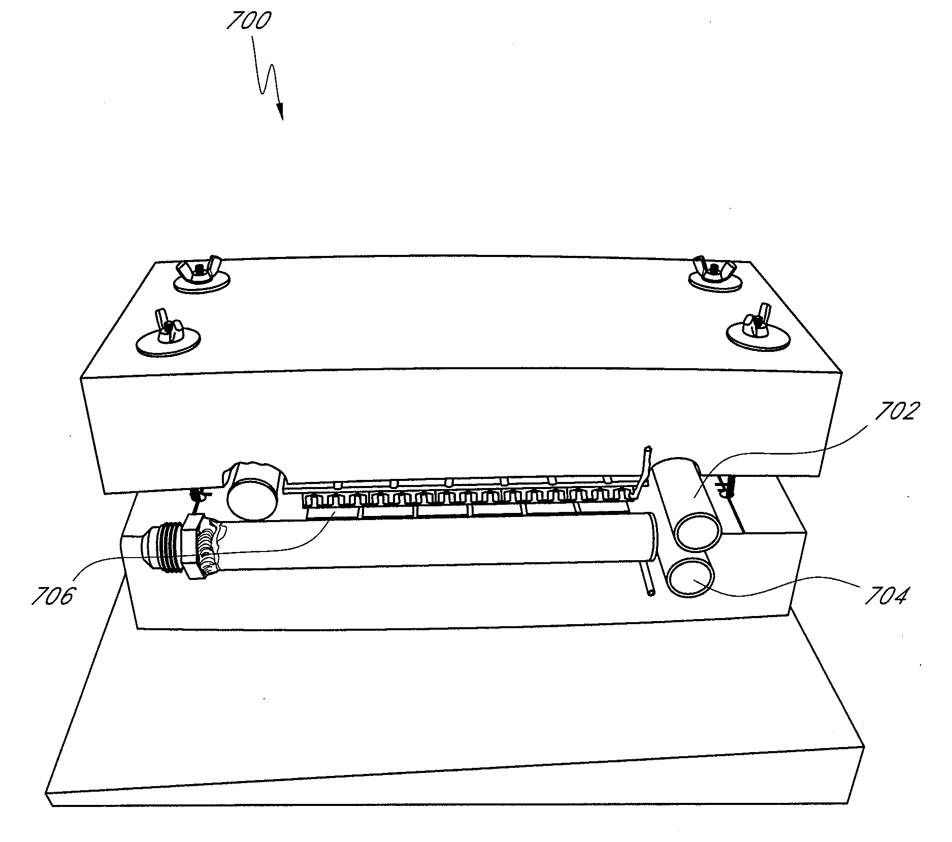
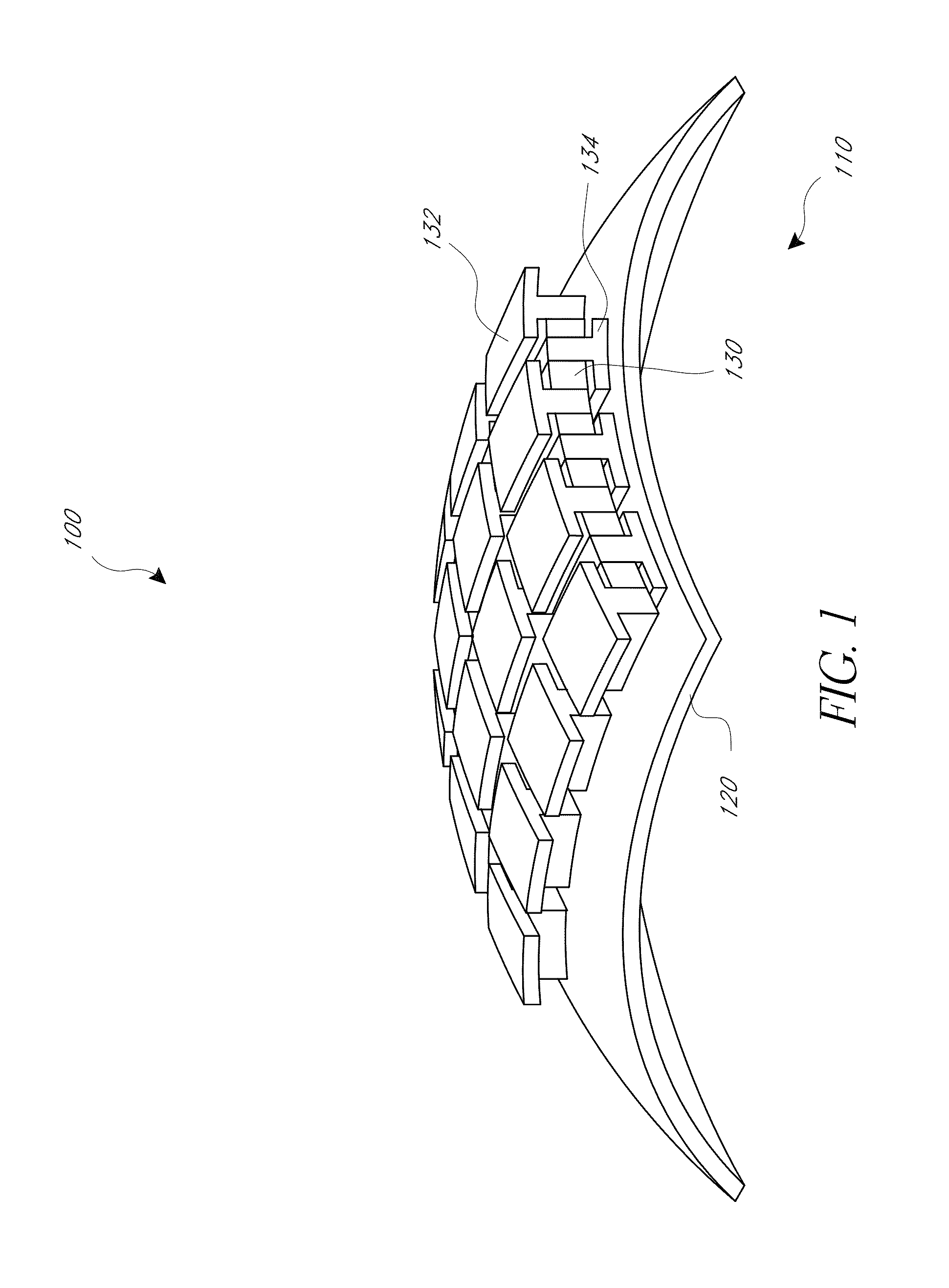
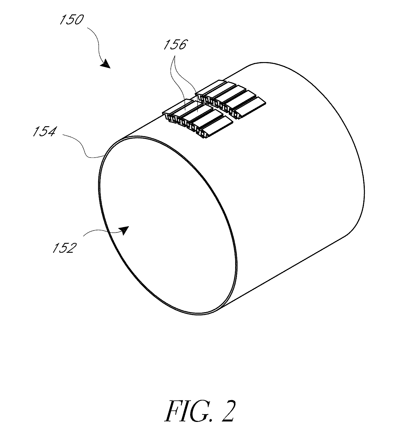
Some embodiments provide a waste heat recovery apparatus including an exhaust tube having a cylindrical outer shell configured to contain a flow of exhaust fluid; a first heat exchanger extending through a first region of the exhaust tube, the first heat exchanger in thermal communication with the cylindrical outer shell; a second region of the exhaust tube extending through the exhaust tube, the second region having a low exhaust fluid pressure drop; an exhaust valve operatively disposed within the second region and configured to allow exhaust fluid to flow through the second region only when a flow rate of the exhaust fluid becomes great enough to result in back pressure beyond an allowable limit; and a plurality of thermoelectric elements in thermal communication with an outer surface of the outer shell, the thermoelectric elements configured to accommodate thermal expansion of the exhaust tube during operation of the waste heat recovery system.

Problems solved by technology

Additional processing of exhaust after its removal from the power plant, including chemical reactions and emissions reduction techniques, can further heat the exhaust and increase the amount of waste heat.
Such thermoelectric generators (TEGs) have not met with commercial success because these devices are not very efficient or flexible in their operation.

Method used


Image

  • Thermoelectric-based power generation systems and methods
  • Thermoelectric-based power generation systems and methods
  • Thermoelectric-based power generation systems and methods

Examples


Embodiment Construction

Although certain preferred embodiments and examples are disclosed herein, inventive subject matter extends beyond the examples in the specifically disclosed embodiments to other alternative embodiments and / or uses, and to modifications and equivalents thereof. Thus, the scope of the claims appended hereto is not limited by any of the particular embodiments described below. For example, in any method or process disclosed herein, the acts or operations of the method or process may be performed in any suitable sequence and are not necessarily limited to any particular disclosed sequence. Various operations may be described as multiple discrete operations in turn, in a manner that may be helpful in understanding certain embodiments; however, the order of description should not be construed to imply that these operations are order dependent. Additionally, the structures, systems, and / or devices described herein may be embodied as integrated components or as separate components. For purpo...


PUM


Abstract

Some embodiments provide a waste heat recovery apparatus including an exhaust tube having a cylindrical outer shell configured to contain a flow of exhaust fluid; a first heat exchanger extending through a first region of the exhaust tube, the first heat exchanger in thermal communication with the cylindrical outer shell; a second region of the exhaust tube extending through the exhaust tube, the second region having a low exhaust fluid pressure drop; an exhaust valve operatively disposed within the second region and configured to allow exhaust fluid to flow through the second region only when a flow rate of the exhaust fluid becomes great enough to result in back pressure beyond an allowable limit; and a plurality of thermoelectric elements in thermal communication with an outer surface of the outer shell.

Description

BACKGROUND1. FieldThis application relates to power generation technology and, in particular, to power generation using thermoelectric devices.2. Description of Related ArtPower equipment commonly produces waste heat in addition to a desired output. For example, a vehicle power plant typically converts fuel energy into mechanical energy and waste heat. At least a portion of the waste heat is often removed from the power plant through an exhaust system. Additional processing of exhaust after its removal from the power plant, including chemical reactions and emissions reduction techniques, can further heat the exhaust and increase the amount of waste heat. For a vehicle having a combustion engine, the exhaust system usually includes tubing that carries exhaust gases away from a controlled combustion inside the engine. The exhaust gases and waste heat can be carried along an exhaust pipe and expelled into the environment.High temperature thermoelectric (TE) power generation has been vi...

Claims


Application Information

Patent Timeline
Patent Type & Authority Applications(United States)
IPC IPC(8): H01L35/28H01L35/30F01N3/20
CPCF01N3/043F01N3/2013F01N3/2053F01N5/025F01N2240/14Y02T10/26F01N2410/02F01N2410/10H01L35/30H01L35/32Y02T10/16F01N2240/36Y02E20/14F28D7/106F28D21/0003Y02T10/12H10N10/00H10N10/13H10N10/17
Inventor BELL, LON E.CRANE, DOUGLAS T.LAGRANDEUR, JOHNHEERDEN, DAVID VAN
Owner GENTHERM INC
Why Eureka
Try Eureka