
System for Preventing Backflow in an Ion Source

a technology of ion source and backflow, which is applied in the field of mass spectrometry, can solve the problems that negatively affect the performance of the mass spectrometer, and achieve the effects of preventing recirculation, preventing backflow, and minimizing turbulence, chemical noise and source turbulen

Active Publication Date: 2011-03-24
THERMO FINNIGAN
View PDF9 Cites 12 Cited by
  • Summary
  • Abstract
  • Description
  • Claims
  • Application Information

AI Technical Summary

Benefits of technology

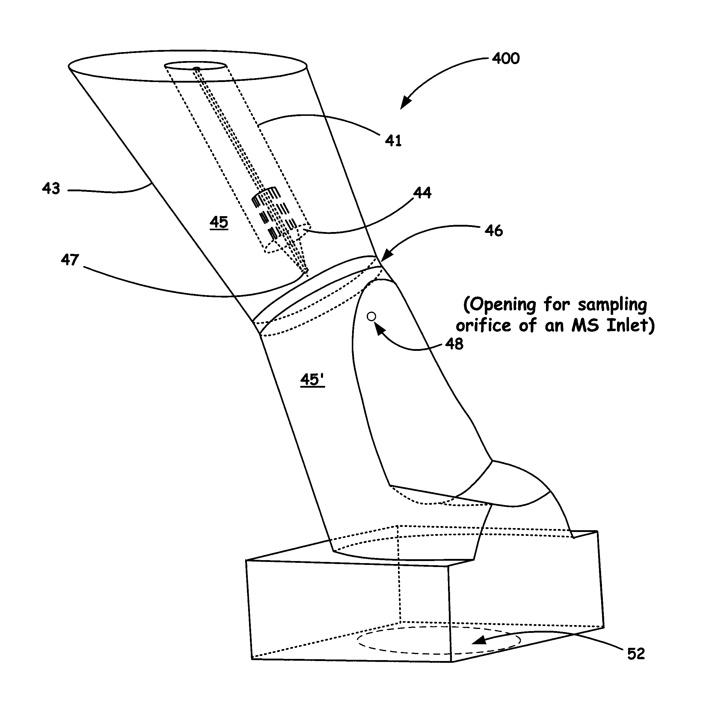
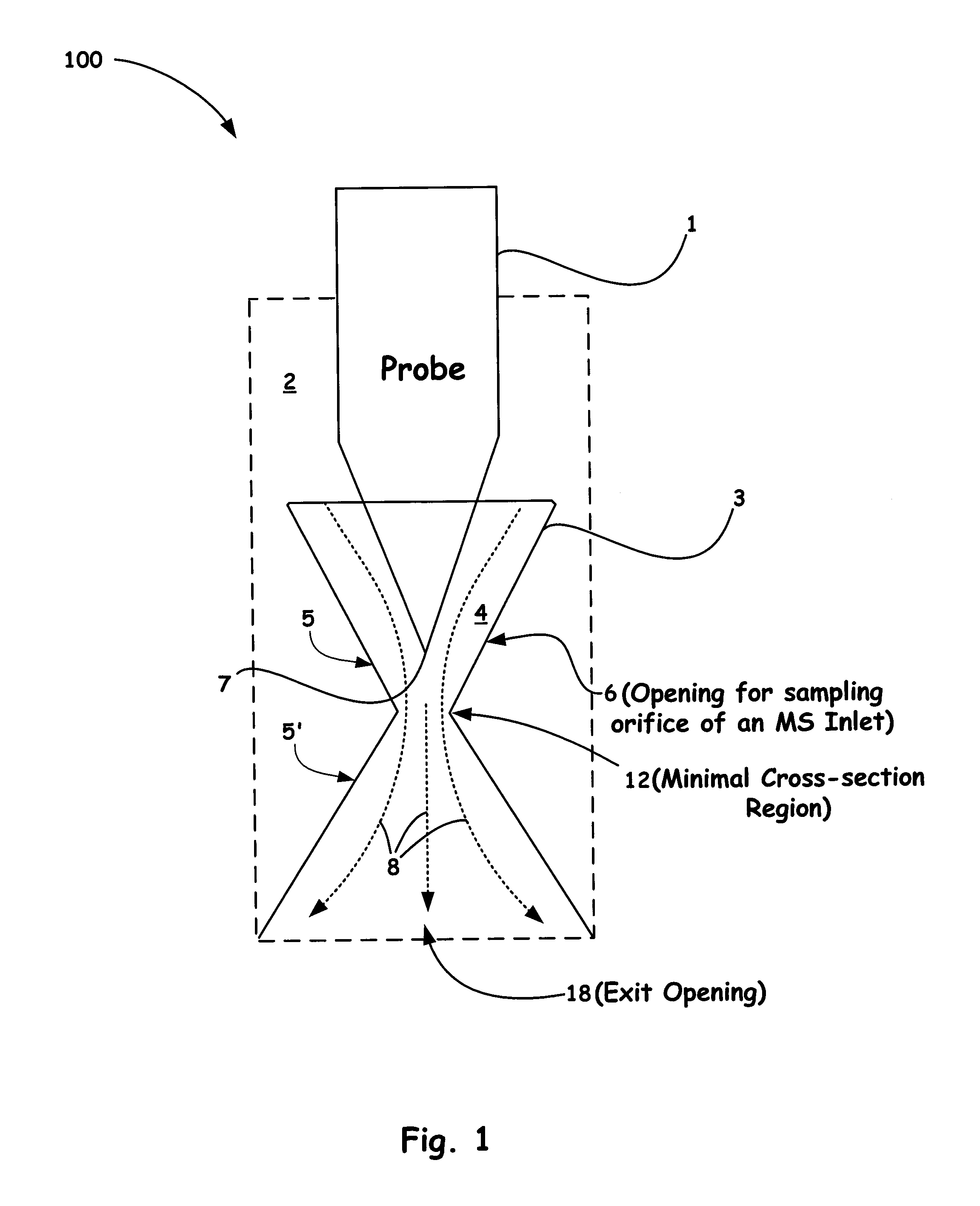
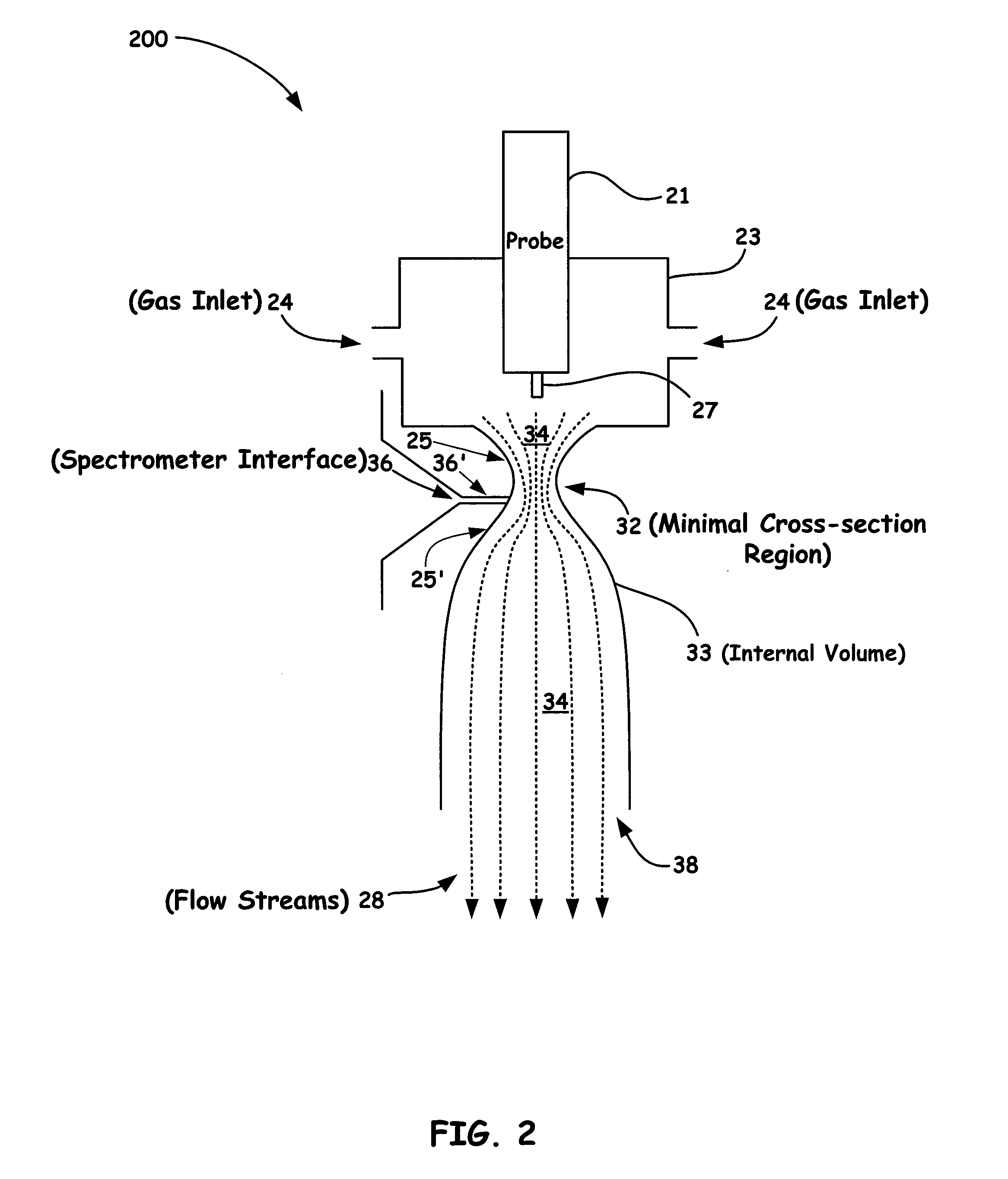
[0010]Accordingly, the present invention provides for a system that prevents backflow in an ion source. Such a system includes: a housing chamber; a continuous flow guide configured within the housing chamber, wherein the continuous flow guide comprises a converging first volume and a diverging second volume coupled at a minimal cross-sectional area; a spray probe disposed within the continuous flow guide and configured to provide a spray plume along a desired axis within the continuous flow guide; one or more auxiliary gas inlets configured to provide an inert gas so as to combine with the spray plume and fill the converging first volume; an exhaust drain port operably coupled to the diverging second volume of the continuous flow guide; and a means to provide for a desired pressure differential within the converging first and the diverging second volume to induce a unidirectional flow past a sampling orifice of a mass spectrometer inlet, the unidirectional flow being further directed out of the exhaust drain port so as to prevent recirculation and thus minimize carryover, chemical noise, and source turbulence.
[0011]In accordance with another aspect of the present invention, a method for preventing backflow in an ion source as part of a mass spectrometer system is introduced. The method includes: providing a continuous flow guide configured within a housing chamber, wherein the continuous flow guide comprises a converging first volume and a diverging second volume coupled at a minimal cross-sectional area; providing a spray probe disposed within the continuous flow guide, the spray probe configured to direct a spray plume that further comprises ionized charged particles of one or more analytes along a desired axis within the continuous flow guide; providing one or more auxiliary gas inlets configured to provide an inert gas so as to combine with the spray plume and fill the converging first volume; and providing a desired pressure differential within the converging first and the diverging second volume to induce a unidirectional flow past a sampling orifice of a mass spectrometer inlet, wherein the unidirectional flow is thereafter directed out of an exhaust drain port so as to prevent recirculation of thus minimize carryover, chemical noise, and source turbulence.
[0012]Accordingly, the present invention provides for a system having an improved source housing / ion source design that includes a substantially reduced internal volume (e.g., a continuous flow guide) with respect to conventional designs. Such an arrangement, as disclosed herein, enables an optimal flow path that results in (1) ease of expansion of the introduced non-turbulent gas towards the exit, (2) prevention of back flows from the exit, and (3) reduced areas of stagnation.

Problems solved by technology

This counter flow contains undesired contaminants and can cause stagnation of the vapor-laden gases which can lead to condensation of droplets on source surfaces and therefore contamination of such surfaces, which can lead to carryover.
This negatively impacts the performance of the mass spectrometer as expressed in the number of samples that can be analyzed per hour.

Method used


Image

  • System for Preventing Backflow in an Ion Source
  • System for Preventing Backflow in an Ion Source
  • System for Preventing Backflow in an Ion Source

Examples


Embodiment Construction

[0019]In the description of the invention herein, it is understood that a word appearing in the singular encompasses its plural counterpart, and a word appearing in the plural encompasses its singular counterpart, unless implicitly or explicitly understood or stated otherwise. Furthermore, it is understood that for any given component or embodiment described herein, any of the possible candidates or alternatives listed for that component may generally be used individually or in combination with one another, unless implicitly or explicitly understood or stated otherwise. Moreover, it is to be appreciated that the figures, as shown herein, are not necessarily drawn to scale, wherein some of the elements may be drawn merely for clarity of the invention. Also, reference numerals may be repeated among the various figures to show corresponding or analogous elements. Additionally, it will be understood that any list of such candidates or alternatives is merely illustrative, not limiting, u...


PUM


Abstract

A system for preventing backflow as part of an ion source arrangement is introduced. Such a system incorporates a novel continuous flow guide within a source, such as an API ion source. In the spray direction, the cross-sectional area that defines the first portion of the internal volume initially decreases in a convergent-like manner and thereafter increases in a divergent-like manner towards the exit opening of the source housing. Such a flow guide has been designed as an integral part of an ion source housing to provide for an optimal unidirectional flow past a sampling orifice of a mass spectrometer inlet. Accordingly, the novel design of the present invention prevents recirculation and thus minimizes carryover, chemical noise, and source turbulence and as an added benefit, enables a user to easily clean such a system during maintenance.

Description

BACKGROUND OF THE INVENTION[0001]1. Field of the Invention[0002]The present invention relates to the field of mass spectrometry, and more particularly to system that includes a novel internal volume (e.g., a continuous flow guide) configuration that provides for an optimal flow path within a mass spectrometer ion source housing.[0003]2. Discussion of the Related Art[0004]In LC-MS mass spectrometry analyte, ions are generated by nebulizing the ion-containing liquid at pressures around atmospheric in a chamber called the ion source housing. Some of this vapor enters the mass spectrometer's vacuum chamber for analysis. The remainder of the vapor, as well as the gases aiding the nebulizing and desolvation processes (sheath and auxiliary) need to exit the source housing through a different opening called a drain. To prevent contamination of surfaces in the source housing which can cause interference with the analysis of subsequent samples, so called carry-over, it is important that the v...

Claims


Application Information

Patent Timeline
Patent Type & Authority Applications(United States)
IPC IPC(8): H01J49/26
CPCH01J49/0445
Inventor WOUTERS, ELOY R.MULLEN, CHRISTOPHERSPLENDORE, MAURIZIO A.ATHERTON, R. PAUL
Owner THERMO FINNIGAN
Learn More