
Position detection apparatus

a technology of positioning detection and detection apparatus, which is applied in the direction of instruments, computing, electric digital data processing, etc., can solve the problems of air bubbles entering the gap between, complicated structure around the connecting portions, and complicated wiring lines, so as to reduce labor and time for wiring, simplify the structure relating to wiring lines, and eliminate labor for connecting signal lines

Active Publication Date: 2011-03-24
WACOM CO LTD
View PDF13 Cites 67 Cited by
  • Summary
  • Abstract
  • Description
  • Claims
  • Application Information

AI Technical Summary

Benefits of technology

The present invention has been made in view of the above circumstances, to provide a position detection apparatus wherein the labor and time for wiring for a detector positioned closely to the surface of the position detection apparatus can be reduced and the structure relating to wiring lines can be simplified.
With the position detection apparatus, where two layers of the bonding agent are provided, since the grooves do not overlap with each other, when a position corresponding to the groove is pointed to (or touched), the portion pointed to can be prevented from being deformed by a great amount.

Problems solved by technology

Therefore, the position detection apparatus has problems that time is required to lead out the wiring lines and that the structure of the connecting portions of the wiring lines is complicated.
Further, if it is tried to increase the area of the detection region of the first detector, then the structure around the connecting portions becomes complicated.
Thus, there is a problem that air bubbles may possibly enter a gap between the first detector and the cover when the cover is adhered.
Besides, where such air bubbles enter, the distance between the surface of the first detector and the human body varies depending upon the presence or absence of air bubbles, and this gives rise to deterioration of the accuracy in position detection.
Further, if convexes and concaves are formed on the cover depending upon the presence or absence of air bubbles, then the user would have a sense of incongruity when touching the surface of the cover, which is not favorable.

Method used


Image

  • Position detection apparatus
  • Position detection apparatus
  • Position detection apparatus

Examples


Embodiment Construction

A position detection apparatus according to an embodiment of the present invention is described below with reference to the drawings.

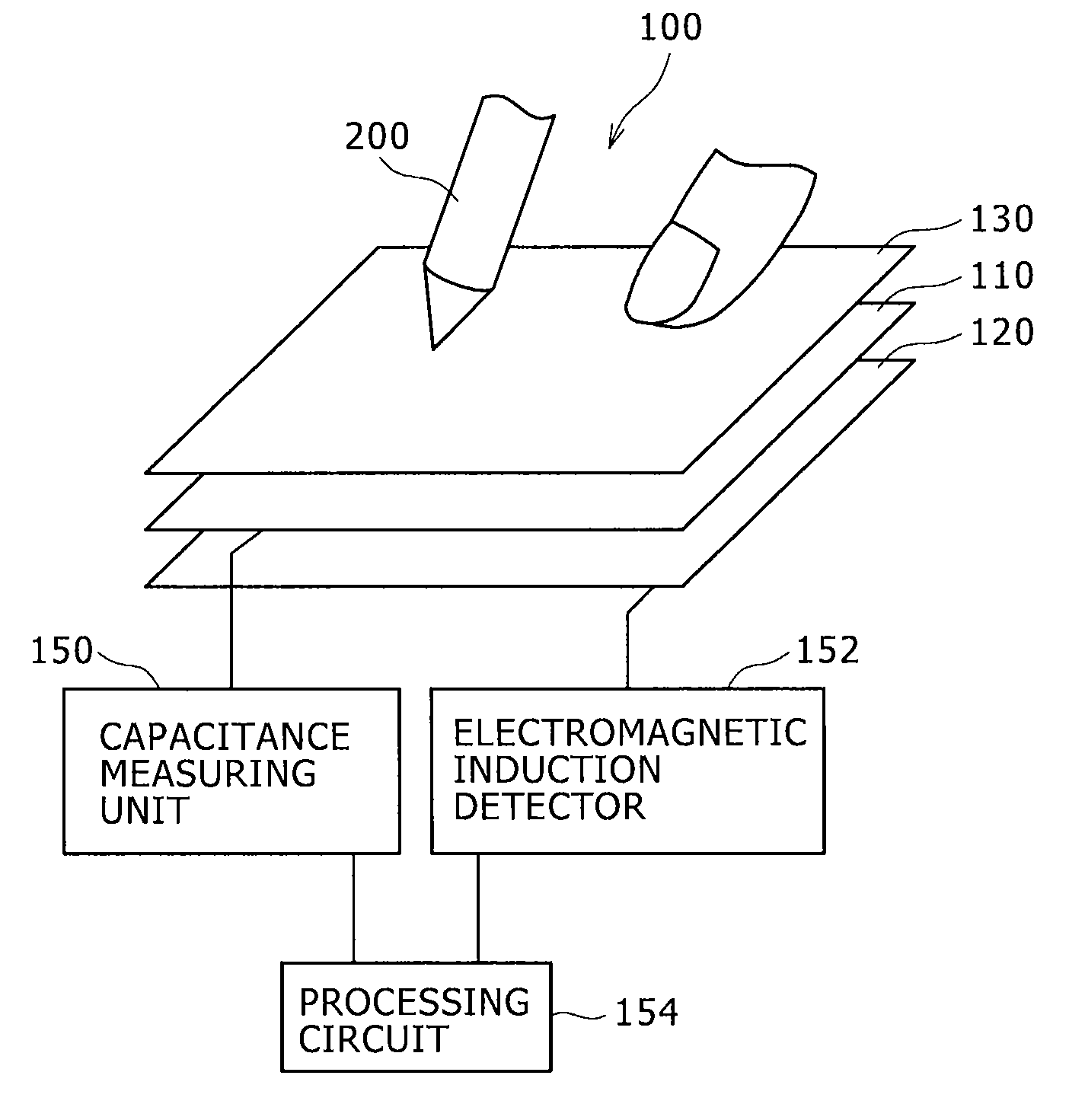
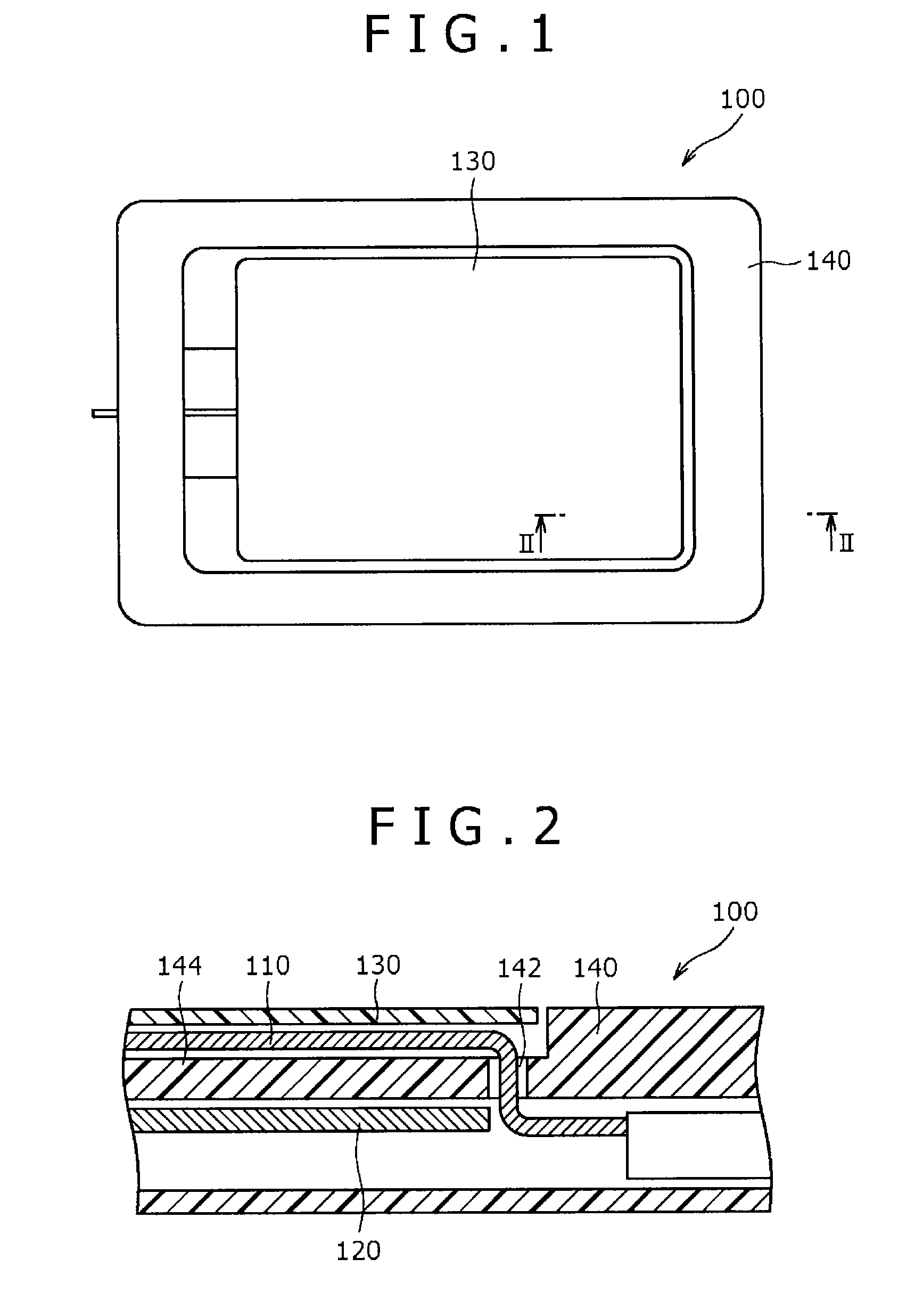
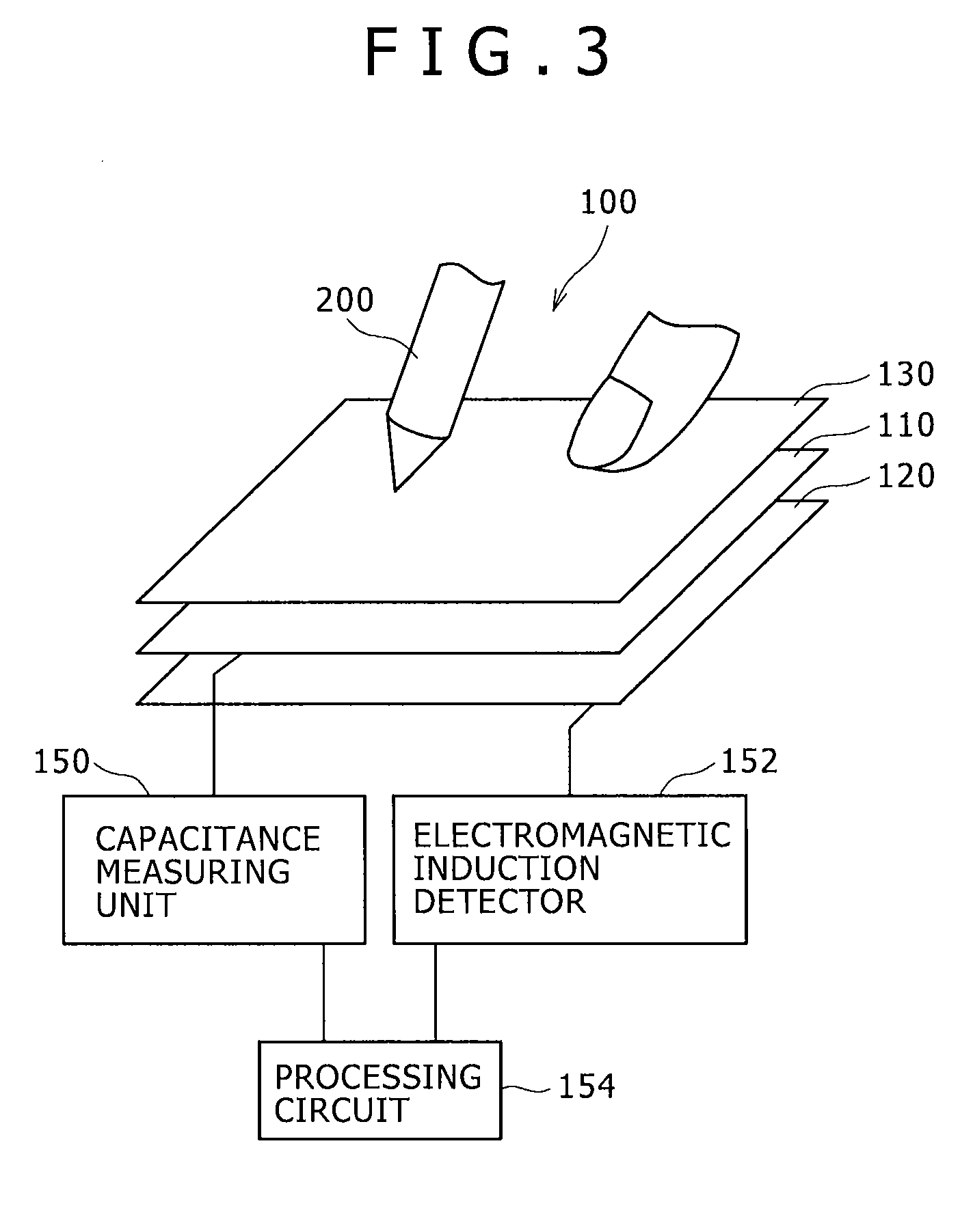
FIG. 1 shows the position detection apparatus of the present embodiment and FIG. 2 shows a cross section taken along line II-II of FIG. 1. Referring to FIGS. 1 and 2, the position detection apparatus 100 of the present embodiment is used to detect a position pointed to by part of the human body such as, for example, a fingertip, or by a position pointer 200 as seen in FIG. 3. The position detection apparatus 100 includes a sensor substrate 110 as a first detector for carrying out position detection using a capacitance system, a magnetic flux detecting substrate 120 as a second detector for carrying out position detection using electromagnetic induction, a sheet member 130 for covering the surface of the sensor substrate 110, a housing 140 having an accommodation unit 144 for accommodating the sensor substrate 110, magnetic flux detecting substrate 120 ...


PUM


Abstract

A position detection apparatus includes: a sensor substrate having a detection region in which position detecting electrodes are formed and a wiring line region in which wiring lines led out from the position detecting electrodes are disposed; a processing circuit connected to the wiring lines of the sensor substrate and configured to carry out a predetermined signal process based on a signal from the sensor substrate; and a housing having the sensor substrate placed thereon and having the processing circuit provided therein; the sensor substrate placed on the housing having a through-hole provided therein in the proximity of the detection region for allowing the wiring lines to be threaded therethrough.

Description

CROSS-REFERENCE TO RELATED APPLICATIONThe present application claims the benefit under 35 U.S.C. §119(a) of Japanese Patent Application No. 2009-218230, filed, Sep. 21, 2009, the entire content of which is incorporated by reference herein.BACKGROUND OF THE INVENTION1. Field of the InventionThis invention relates to a position detection apparatus which carries out position detection based on capacitance.2. Description of the Related ArtA position detection apparatus is conventionally known wherein an inputting unit including a first detector utilizing capacitance and a second detector utilizing electromagnetic induction disposed in a superposed relationship with each other is fitted in an opening of a case. A position detection apparatus of the type described is disclosed, for example, in Japanese Patent Laid-Open No. 2009-162538 (pages 4 to 8 and FIGS. 1 to 11) (hereinafter referred to as Patent Document 1). In the position detection apparatus of the type described, the first detect...

Claims


Application Information

Patent Timeline
Patent Type & Authority Applications(United States)
IPC IPC(8): G06F3/041
CPCG06F3/0416G06F3/046G06F3/044G06F3/03547G06F3/04164G06F3/0445G06F3/0446G06F2203/04103G06F2203/04106
Inventor YOKOTA, MASARUMUNAKATA, HIROSHISATO, YUTAKANEDA, TAKENORINAKATA, TAKAAKI
Owner WACOM CO LTD
Learn More