Apparatus and method for irradiating a medium

a technology of irradiation and apparatus, applied in the field of apparatus and a method for irradiation of medium, can solve the problems of loss of directionality of light as well as information associated, difficult to extract detailed internal information about a medium, and difficult to obtain internal information through detection of scattered ligh

Inactive Publication Date: 2011-03-24
CANON KK
View PDF26 Cites 48 Cited by
  • Summary
  • Abstract
  • Description
  • Claims
  • Application Information

AI Technical Summary

Problems solved by technology

This is because the scattered light does not propagate in a straight line through the medium, with the random paths of the scattered light causing the loss of directionality of the light as well as information associated therewith.
Thus, it can be difficult to extract detailed internal information about a medium in which such scattering occurs via the detection of the scattered or diffused visible light.
For example, in medical applications that deal with biological tissues, the scattering that occurs in passing light through the tissues may make it difficult to obtain internal information via detection of the scattered light.
However, U.S. Patent Application Publication No. 2009 / 0009834 discloses that the optical phase conjugation method described therein is only capable of focusing light at a region just behind the scattering medium, where the incident light originally impinges.
Therefore, as described therein, the method is not being capable of focusing light arbitrarily at any specific point inside the scattering medium.
In many cases, such as in a high scattering medium including biological tissues, this situation is not practical.
For example, in a strong scattering medium, the multiple scattering processes that can occur therein may make it quite difficult to specify which scatterers are dominant and are mainly responsible for causing the forward scattering (and sometimes the scattering may not even be in the forward direction).
It can thus be difficult to retrace and illuminate the light path created by the multiple scattering processes using optical phase conjugation.
Such multiple scattering processes may be caused, for example, by the presence of too many of the scatterers in the medium.
Furthermore, it can be challenging to determine the exact location where the optical phase conjugation retraces to focus in such a scattering medium, because the location of the “strong scatterers” inside the medium are usually not known, even when the light is focused in a general vicinity of the “strong scatters”.

Method used


Image

  • Apparatus and method for irradiating a medium
  • Apparatus and method for irradiating a medium
  • Apparatus and method for irradiating a medium

Examples


fourth embodiment

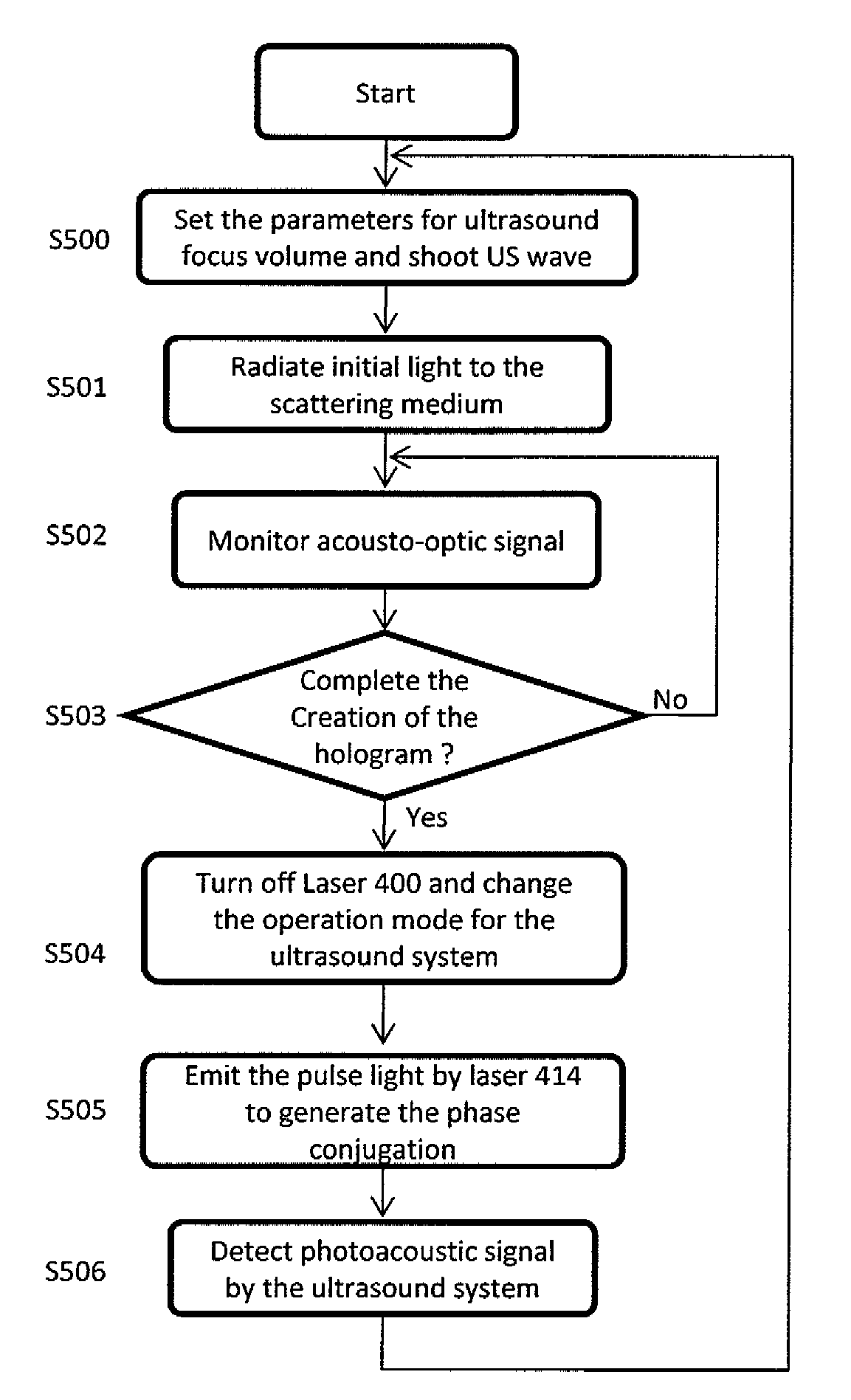
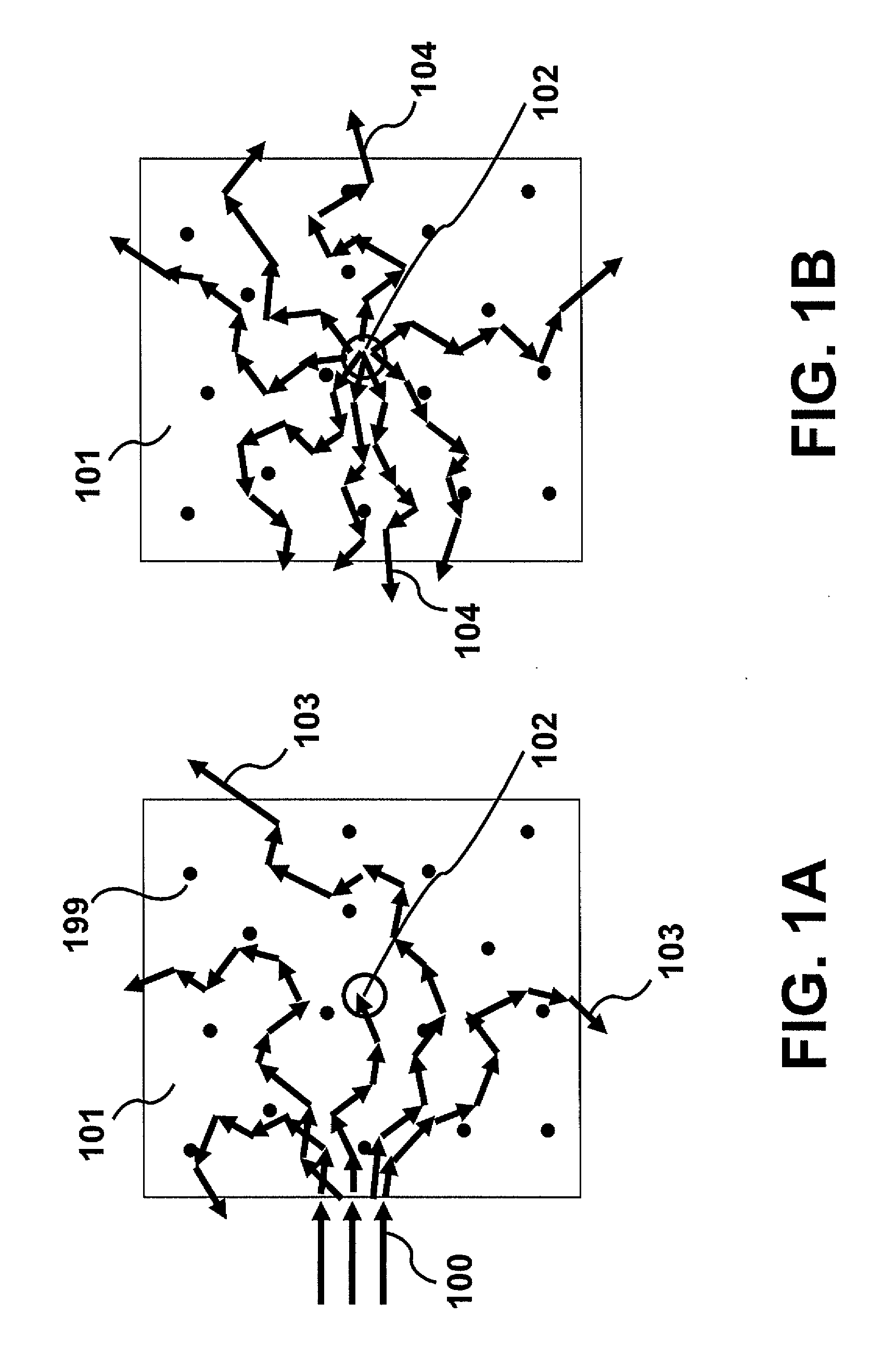
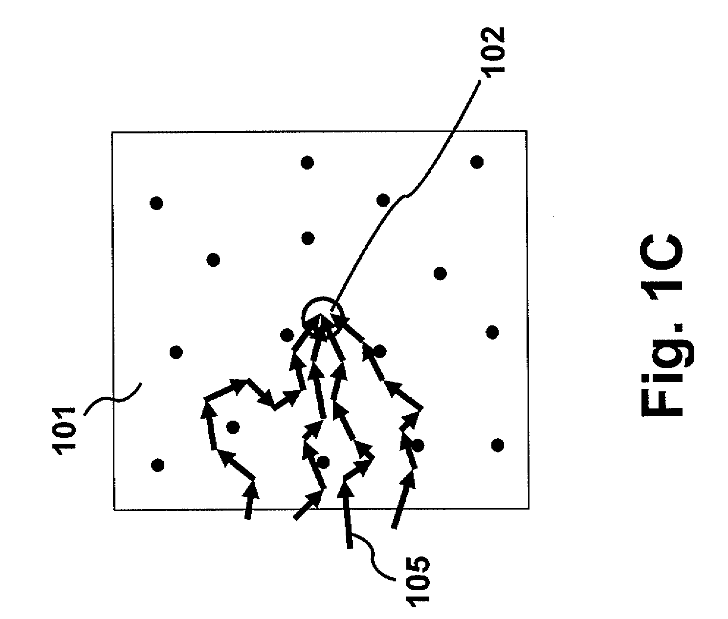
[0035]Once the wavefront corresponding mainly to this frequency-shifted light 104 is recorded and is played back with its phase conjugation 105, this phase conjugation can retrace its trajectory and reach or travel toward the position 102 shown in FIG. 1C. To realize a phase conjugation (i.e., a reconstructed wave, a phase conjugation wave), holography can be employed. In holography, an interference pattern generated by interference between the modulated light and a reference wave can be recorded in a holographic material, and also the interference pattern can be detected by a photodetector, such as a CCD sensor and a CMOS sensor. A technique to detect the interference pattern by the photodetector is referred to as digital holography. The phase conjugate wave can be generated based on the obtained information corresponding to the interference pattern. For example, when the interference pattern is recorded in the holographic material, the conjugate wave can be generated by a pump lig...

third embodiment

[0050]The light emitted by the light source 200 eventually illuminates the holographic material 206 as a pump light beam 213 in a direction substantially opposite to that of the reference light beam 212, as shown in FIG. 2B. Alternatively, another light source for the pump light can also be employed instead of the light source 200, as described in a The first irradiating unit, after the information is recorded on the holographic material, may thus be configured to irradiate the holographic material without passing through the medium 209. The pump light beam 213 may be a continuous wave or a pulse wave.

[0051]This pump light generates a phase conjugation wave 210′ of the recorded wavefront inside the holographic material 206. The phase conjugation wave 210′ propagates toward the scattering medium 209 and enters the medium 209. This phase conjugation wave 210′ can retrace its original trajectory experienced at the recording step in the scattering medium 209, and go back to the ultraso...

first embodiment

[0059]An irradiating apparatus and method according to the present invention will be described below. FIG. 3A and 3B are schematic diagrams illustrating an exemplary configuration of a recording step (FIG. 3A) and a reproducing step (FIG. 3B), respectively.

[0060]The first embodiment includes an acousto-optic imaging technique. A laser 300 emits an initial light and the initial light is split into an incident light beam 314 and a reference light beam 315 by a beam splitter 301 in FIG. 3A. The incident light beam 314 and the reference light beam 315 enter AOM 302 and AOM 305, respectively. The frequencies of those two AOMs are typically 50 MHz to 80 MHz, and are slightly different by an amount equal to the frequency applied to an ultrasound system 311, which ranges from approximately 1 to tens of megahertz. The role of these AOMs may be the same as described above.

[0061]A lens system 303 controls the beam size of the incident light 314, and a movable mirror 304 controls the incident p...


PUM


Abstract

A method for irradiating a medium includes irradiating the medium with an electromagnetic wave which is scattered in the medium and modulated in frequency at a position in the medium; obtaining information corresponding to an interference pattern generated by interference between the modulated electromagnetic wave and a reference wave; and generating a phase conjugate wave, based on the obtained information, which irradiates the medium.

Description

BACKGROUND OF THE INVENTION[0001]1. Field of the Invention[0002]The present invention relates to an apparatus and a method for irradiating a medium.[0003]2. Description of the Related Art[0004]Light scattering is one of the essential matters that can obstruct and even prevent viewing inside of, or through, a medium where scattering processes are dominant. This is because the scattered light does not propagate in a straight line through the medium, with the random paths of the scattered light causing the loss of directionality of the light as well as information associated therewith. Thus, it can be difficult to extract detailed internal information about a medium in which such scattering occurs via the detection of the scattered or diffused visible light. For example, in medical applications that deal with biological tissues, the scattering that occurs in passing light through the tissues may make it difficult to obtain internal information via detection of the scattered light.[0005...

Claims


Application Information

Patent Timeline
Patent Type & Authority Applications(United States)
IPC IPC(8): A61B6/00
CPCG01N21/4795G03H2001/2213G03H1/02G03H1/04G03H1/2645G03H1/28G03H2001/0212G03H2001/0467G03H2001/2244G03H2001/2655G03H2210/62G03H2222/10G03H2260/36G03H1/2205G03H1/0005G01N21/1717G01N2021/1727A61B5/0097
Inventor MASUMURA, TAKAHIRO
Owner CANON KK
Why Eureka
Try Eureka