Busbar and electrical junction box incorporating the same

a busbar and junction box technology, applied in the direction of gaseous cathodes, electrical apparatus casings/cabinets/drawers, coupling device connections, etc., can solve the problems of low yield ratio and mountability, poor electrical conductivity of pure copper, and large dimensions of conventional busbars with relatively large dimensions, etc., to prevent positional deviation, reduce cavity wall height, and facilitate terminal fittings. , the effect of reducing the height of the cavity wall

Active Publication Date: 2011-03-31
YAZAKI CORP
View PDF5 Cites 19 Cited by
  • Summary
  • Abstract
  • Description
  • Claims
  • Application Information

AI Technical Summary

Benefits of technology

[0018]In view of the above-identified drawbacks, an object of the present invention is to provide a busbar that ensures improves reliable connection and capable of allowing a large current to flow therein even when dimensions of the busbar are reduced.
[0026]According to the present invention with the preferable feature, the first busbar component and the second busbar component are connected in parallel with each other (which will be described in detail in the exemplary embodiment) so as to reduce the resistance between the welding portions to allow larger current to flow.
[0028]According to the present invention with the above feature, the electrical junction box includes the busbar having reduced dimensions. Accordingly, it is made possible to provide an electrical junction box with the height of the cavity wall reduced. By making the height of the cavity wall smaller, the cavity wall does not interfere with mounting operation of the junction box, making it easier to attach the terminal fittings thereto.
[0029]Further, since the present invention includes the busbar whose male-terminal-connecting portion is stably positioned, it is possible to prevent positional deviation of the male-terminal-connecting portion with respect to mounting to the cavity and the connection with the male terminal of a mating component.

Problems solved by technology

However, since the copper alloy is made of copper as the principal component and other metal or non-metal material, its electric conductivity is inferior to that of pure copper.
This means that the busbar has relatively large dimensions.
Such a conventional busbar having relatively large dimensions may not be compatible with high yield ratio and mountability, i.e., the degree of how the busbar can be readily mounted to the electrical junction box.
In addition, a busbar made of pure copper in view of improved electric conductivity may fail to have sufficient spring property, and such insufficient spring property makes it difficult for the male-terminal-connecting portion to ensure reliable connection.

Method used


Image

  • Busbar and electrical junction box incorporating the same
  • Busbar and electrical junction box incorporating the same
  • Busbar and electrical junction box incorporating the same

Examples


Embodiment Construction

[0038]Although the following description contains specific implementation details for the purposes of illustration, those skilled in the art will appreciate that various variations and alterations to the following details fall within the scope of the present invention. Accordingly, the following exemplary embodiment of the invention is set forth without imposing limitations upon the claimed invention.

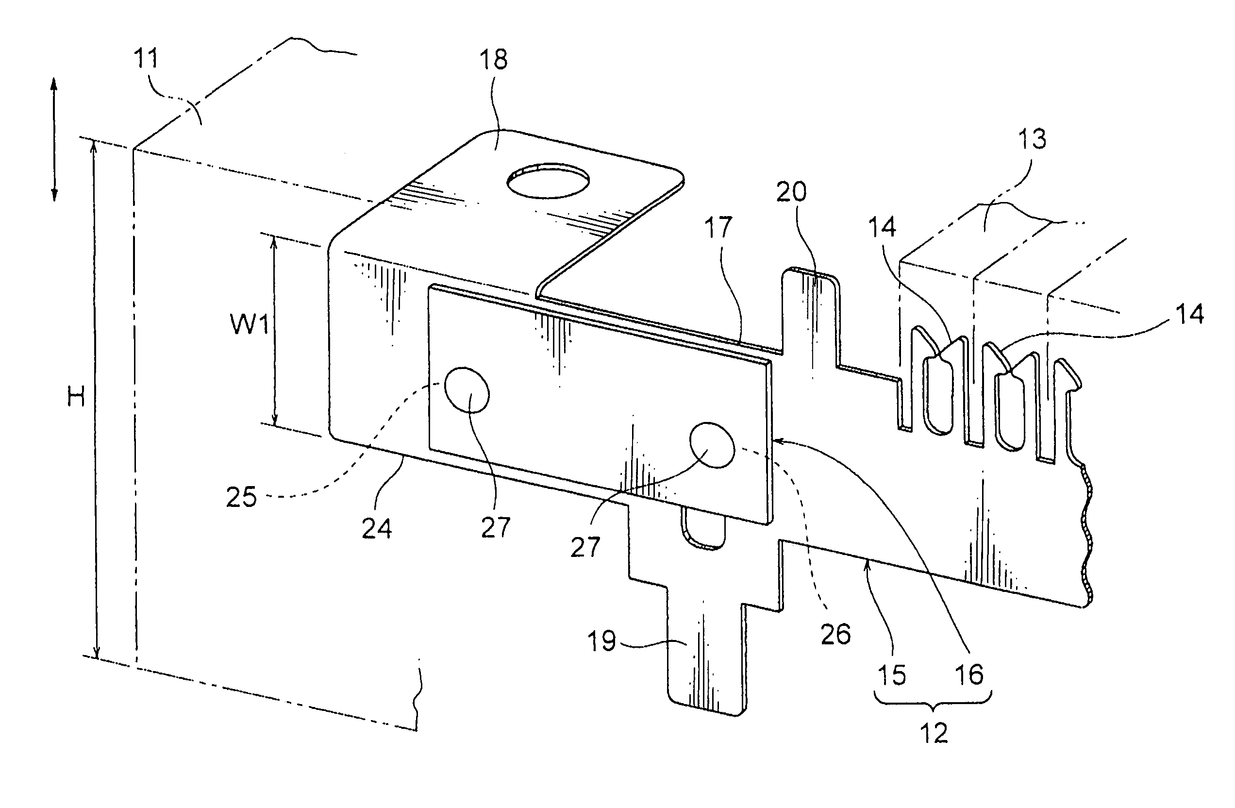
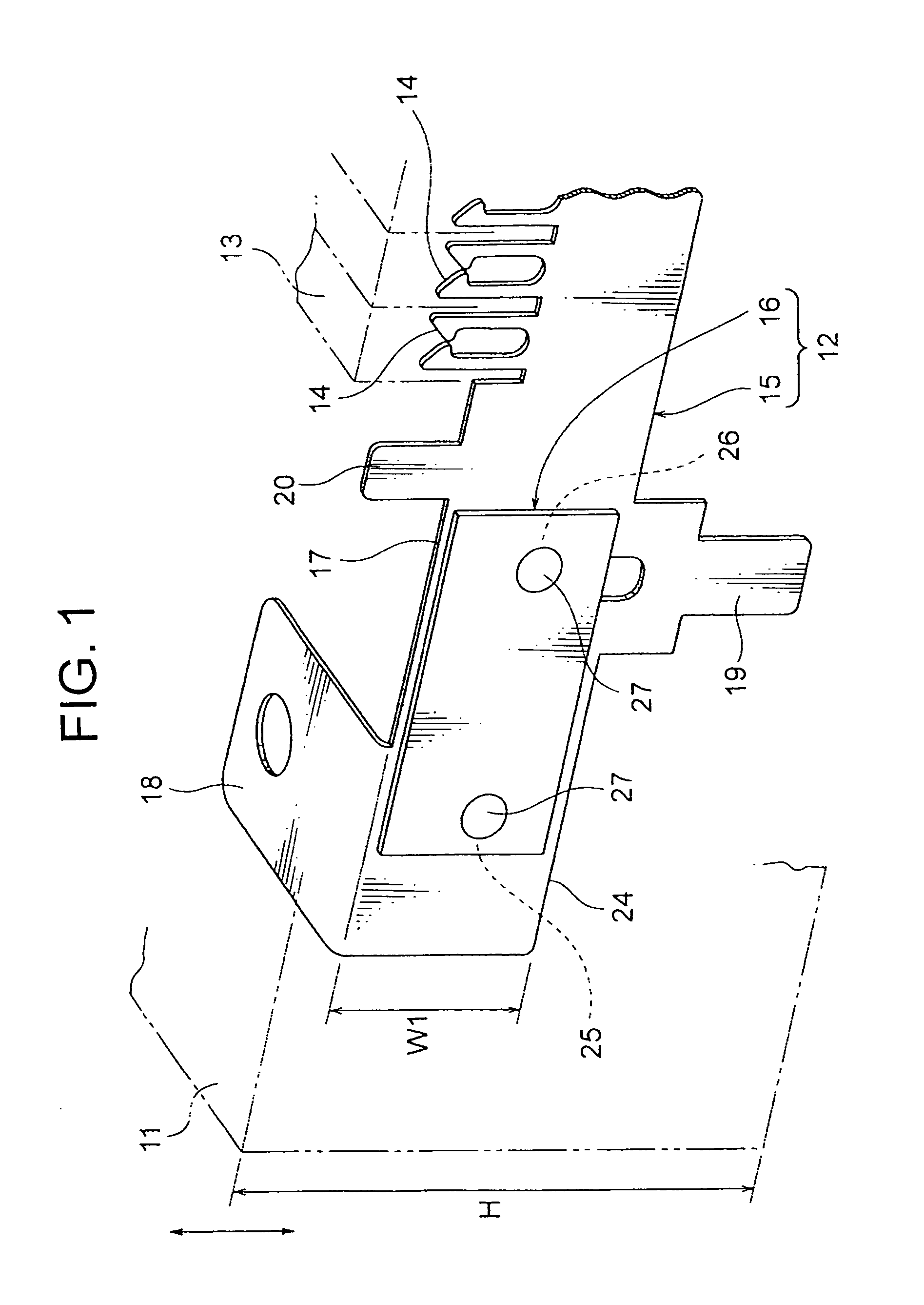
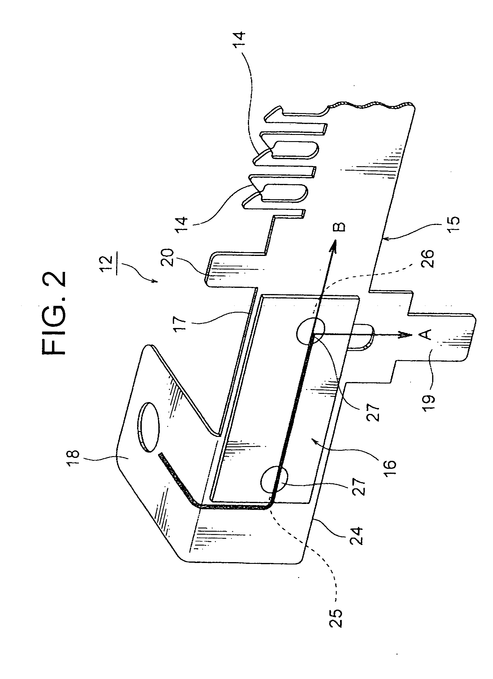
[0039]Referring to FIG. 1, there is shown a perspective view of a busbar 12 according to the exemplary embodiment of the present invention and an electrical junction box incorporating the sane busbar 12.

[0040]First, the configuration of the electrical junction box is described in detail with reference to FIG. 1, which schematically illustrates a junction box body 11 of the electrical junction box.

[0041]The electrical junction box may be a relay box (R / B) mounted in an engine room of an automobile and comprise the junction box body 11, an upper cover (not shown) adapted to be brought int...


PUM


Abstract

A busbar includes a first busbar component as a busbar body and a second busbar component connected thereto. The first busbar component is made of an electrically-conductive metal material having superior spring property. The first busbar component includes a male-terminal-connecting portion for clamping a male terminal of a device and a power input part provided upstream of the male-terminal-connecting portion. The second busbar component is made of an electrically-conductive metal material having electrical conductivity superior to that of the first busbar component. The second busbar component is connected to the first busbar component via a first section of the second busbar component in register with the power input part of the first busbar component and a second section of the second busbar component in register with a portion of the first busbar component, the portion being upstream of the male-terminal-connecting portion at which the current is divided.

Description

CROSS REFERENCE TO RELATED APPLICATION[0001]This application claims priority to Japanese Patent Application No. 2009-226017 filed on Sep. 30, 2009, the contents of which are fully incorporated herein by reference.BACKGROUND OF THE INVENTION[0002]1. Field of the Invention[0003]The present invention relates to a busbar through which a large current flows, the busbar including male-terminal-connecting portion having spring property, and to an electrical junction box incorporating this busbar.[0004]2. Description of the Related Art[0005]An electrical junction box, e.g., a relay box (R / B) mounted in an automobile or other vehicles comprises a busbar that includes male-terminal-connecting portions for connecting male tab terminals (male terminals) of a miniature fuse and a blade-type fuse to the busbar.[0006]The male-terminal-connecting portion has a tuning-fork-like shape for clamping the male tab terminal to provide electrical connection.[0007]The busbar is made of an electrically-condu...

Claims


Application Information

Patent Timeline
Patent Type & Authority Applications(United States)
IPC IPC(8): H02G3/08H02G5/00
CPCH01R9/24H01R25/00H01R13/112H01R13/04
Inventor SATO, HISASHIMOCHIZUKI, TAKAHIRO
Owner YAZAKI CORP
Why Eureka
Try Eureka