Servo-assisted scanning beam display systems using fluorescent screens

Active Publication Date: 2011-03-31
PRYSM SYST INC
View PDF21 Cites 13 Cited by
  • Summary
  • Abstract
  • Description
  • Claims
  • Application Information

AI Technical Summary

Benefits of technology

In another implementation, a method for controlling a scanning beam display system is described. In this method, a beam of excitation light modulated with optical pulses is scanned on a screen with parallel fluorescent stripes in a beam scanning direction perpendicular to the fluorescent stripes to excite the fluorescent strips to emit visible fluorescent light which forms images. A temporal variation in timing of the optical pulses in the beam of excitation light is provided to advance or delay a spatial position of each op

Problems solved by technology

Although CRT displays can produce vivid colors and bright images with high resolutions, the use of cathode-ray tubes places

Method used


Image

  • Servo-assisted scanning beam display systems using fluorescent screens
  • Servo-assisted scanning beam display systems using fluorescent screens
  • Servo-assisted scanning beam display systems using fluorescent screens

Examples


Embodiment Construction

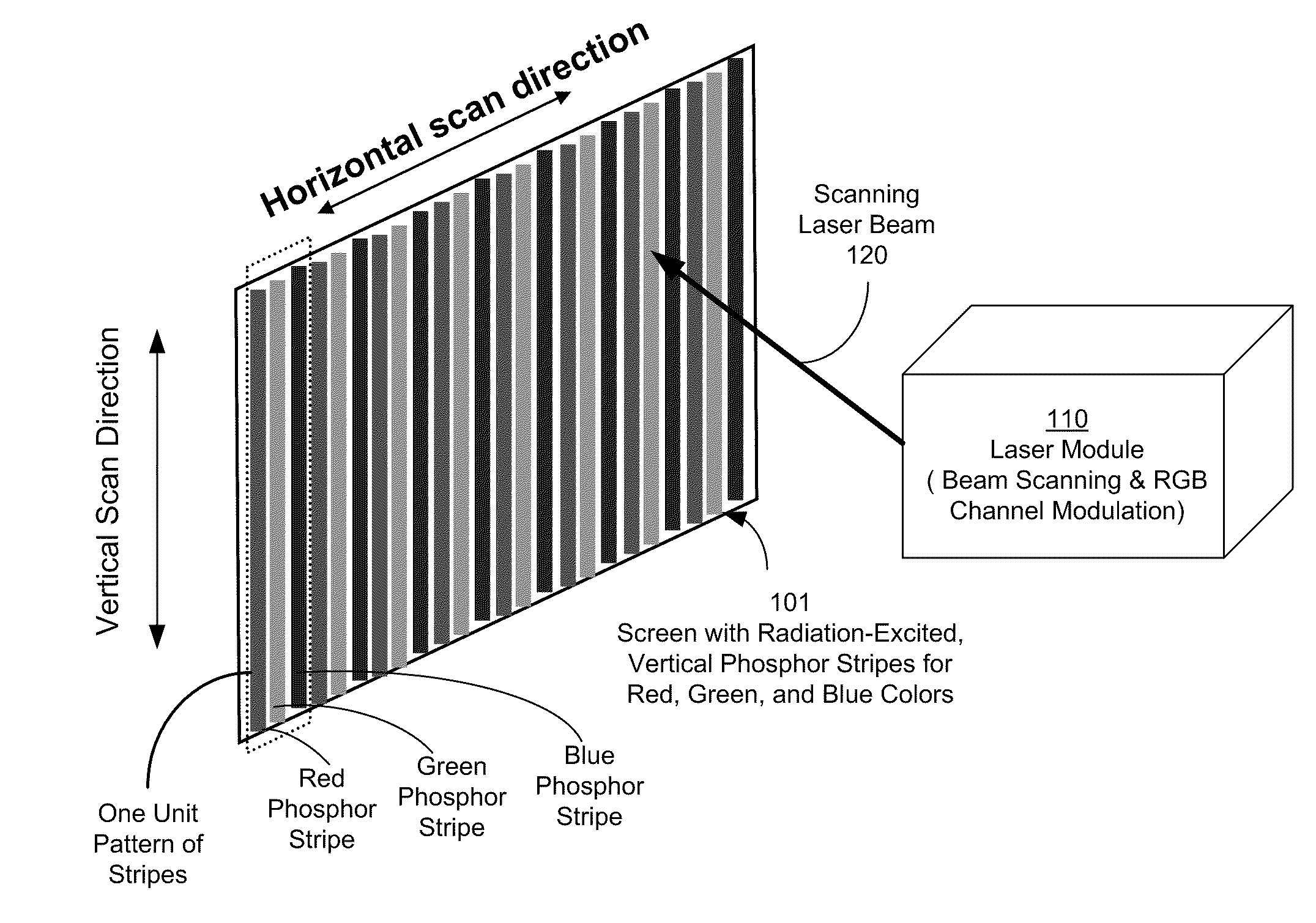
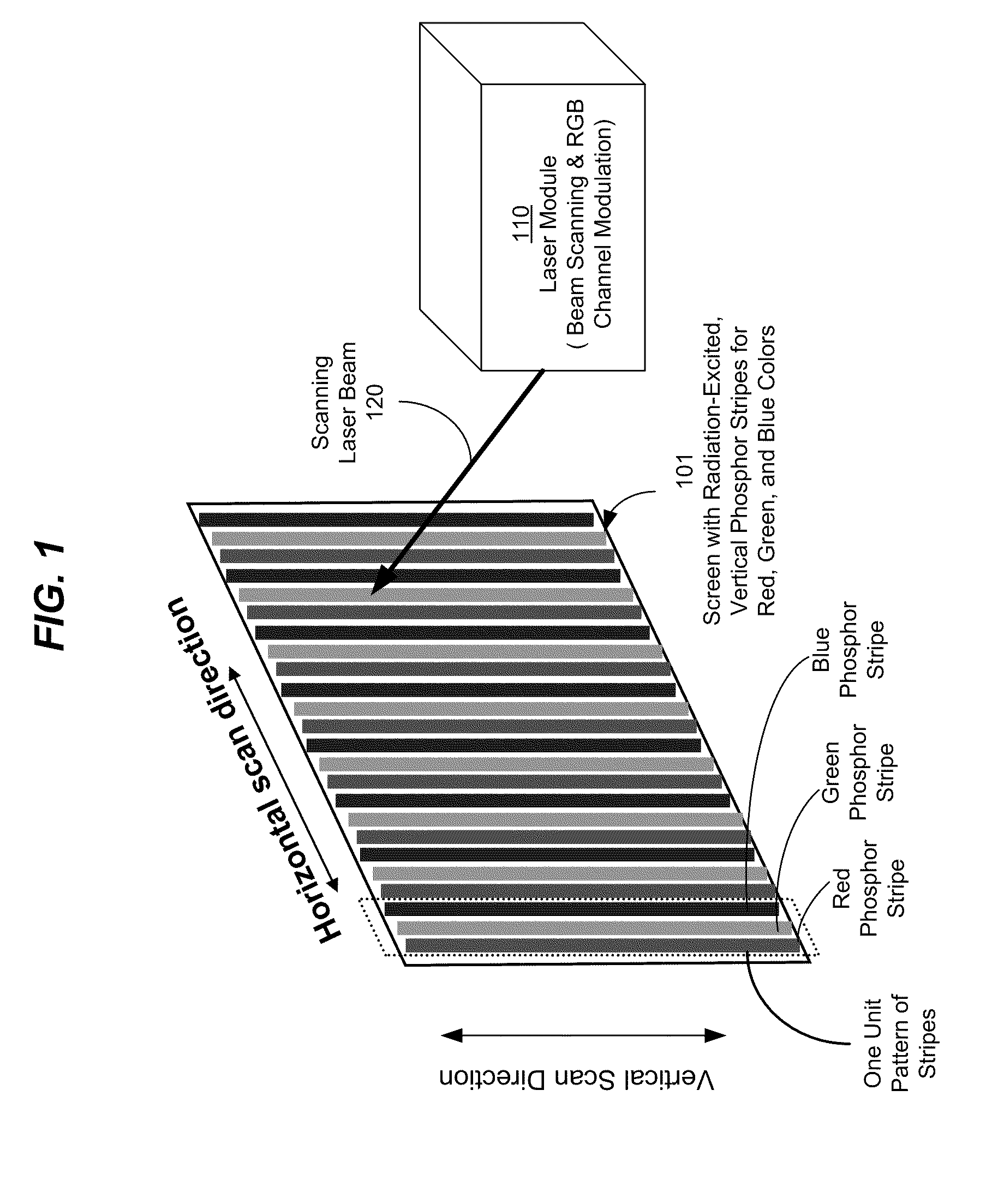
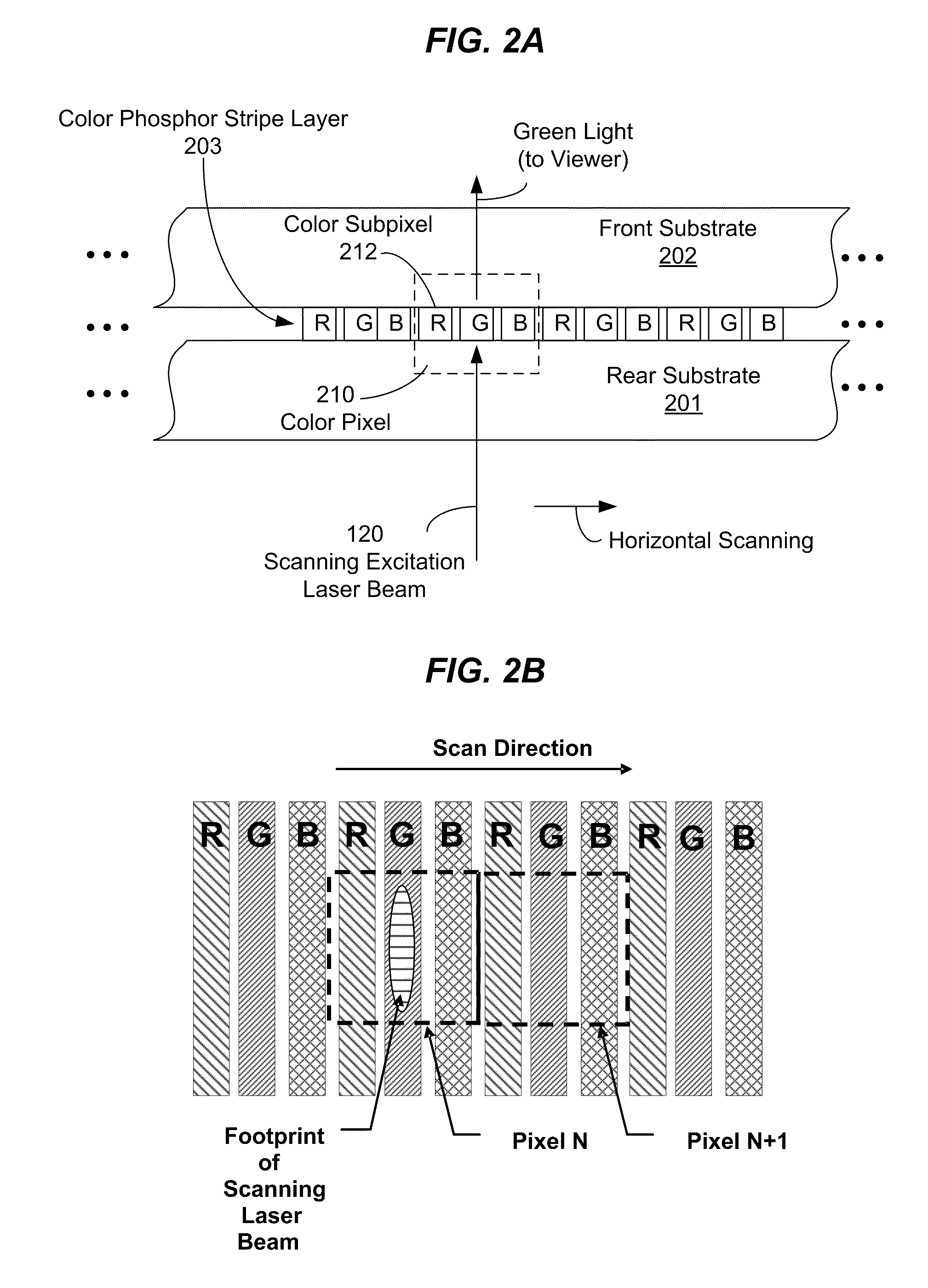
This application describes scanning beam display systems and devices that use fluorescent screens with fluorescent materials to emit light under optical excitation to produce images, including laser vector scanner display devices and laser video display devices that use laser excitable fluorescent screens to produce images by absorbing excitation laser light and emitting colored light. Various examples of screen designs with fluorescent materials are described. Screens with phosphor materials under excitation of one or more scanning excitation laser beams are described in detail and are used as specific implementation examples of optically excited fluorescent materials in various system and device examples in this application. In one implementation, for example, three different color phosphors that are optically excitable by the laser beam to respectively produce light in red, green, and blue colors suitable for forming color images can be formed on the screen as repetitive red, gre...


PUM


Abstract

Methods and systems for improving imaging quality and power efficiency of scanning beam display systems using fluorescent screens are disclosed. In various embodiments, beam shaping mechanisms for maximizing overlap between the beam cross-section and the florescent element corresponding to each color sub-pixel of the screen, as well as pulse width and timing adjustments, are introduced to reduce imaging noise and improve power efficiency of the display system.

Description

BACKGROUNDThis application relates to display systems that use screens with fluorescent materials to emit colored light under optical excitation, such as laser-based image and video displays and screen designs for such displays.Many image and video displays are designed to directly produce color images in different colors, such as red, green and blue and then project the color images on a screen. Such systems are often referred to as “projection displays” where the screen is simply a surface to make the color images visible to a viewer. Such projection displays may use white light sources where white beams are filtered and modulated to produce images in red, green and blue colors. Alternatively, three light sources in red, green and blue may be used to directly produce three beams in red, green and blue colors and the three beams are modulated to produce images in red, green and blue. Examples of such projection displays include digital light processing (DLP) displays, liquid crysta...

Claims


Application Information

Patent Timeline
IPC IPC(8): G09G3/22
CPCG02B26/101G09G3/02H04N9/3129G09G2320/0693G09G2310/0235
Inventor HAJJAR, ROGER A.BURROUGHS, ALAN C.PAJDOWSKI, MARK A.KENT, DAVID L.UEBBING, JOHNMALYAK, PHILLIP H.KRALL, DONALD A.
Owner PRYSM SYST INC
Why Eureka
Try Eureka