Touch Screen Border Regions

Active Publication Date: 2011-03-31
APPLE INC
View PDF28 Cites 71 Cited by
  • Summary
  • Abstract
  • Description
  • Claims
  • Application Information

AI Technical Summary

Benefits of technology

[0006]This relates to border regions of touch screens, and in particular, to compacting elements of the touch sensing and display systems in border regions more efficiently. Border regions of touch screens can include circuit elements of the touch sensing system, e.g., conductive lines that connect touch sensors in an active area of the touch screen to a touch processor elsewhere in the system. Border regions of touch screens can also include circuit elements of the display system, e.g., gate drivers that drive gate lines to address rows of display pixels in an LCD display. In some embodiments, a touch screen border region can include different regions, such as a region in which only certain types of circuit elements can be formed, i.e., a restricted structure region, and a region in which any type of circuit element can be formed, i.e., an unconstrained region. Various embodiments described below disclose arrangements

Problems solved by technology

As touch sensing and display circuitry becomes more closely integrated in border regio

Method used


Image

  • Touch Screen Border Regions
  • Touch Screen Border Regions
  • Touch Screen Border Regions

Examples


Embodiment Construction

[0032]In the following description of example embodiments, reference is made to the accompanying drawings in which it is shown by way of illustration specific embodiments that can be practiced. It is to be understood that other embodiments can be used and structural changes can be made without departing from the scope of the various embodiments.

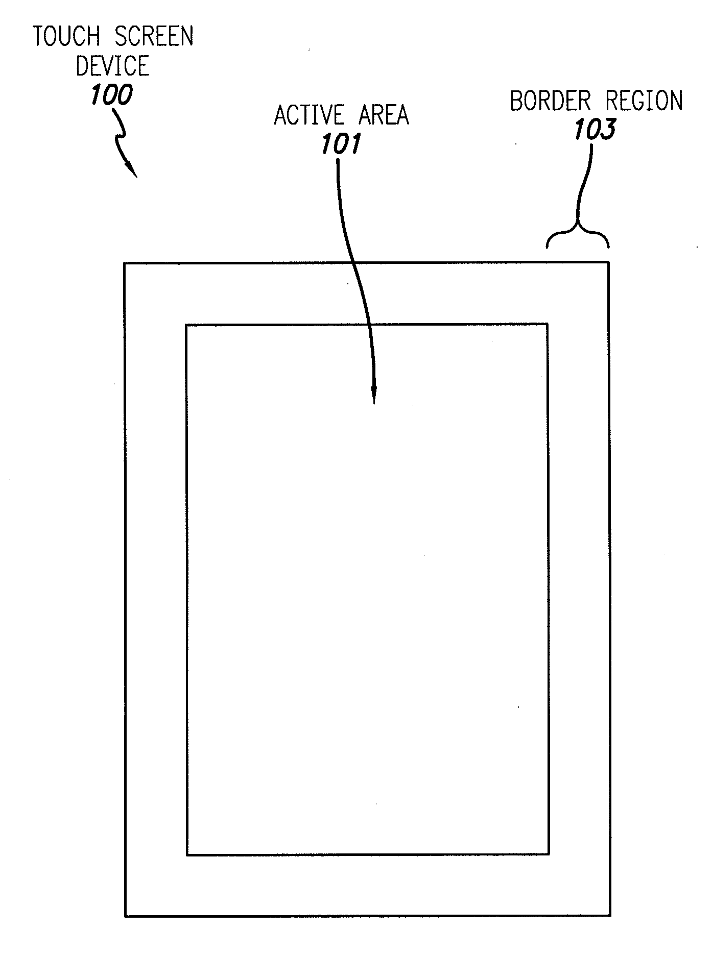
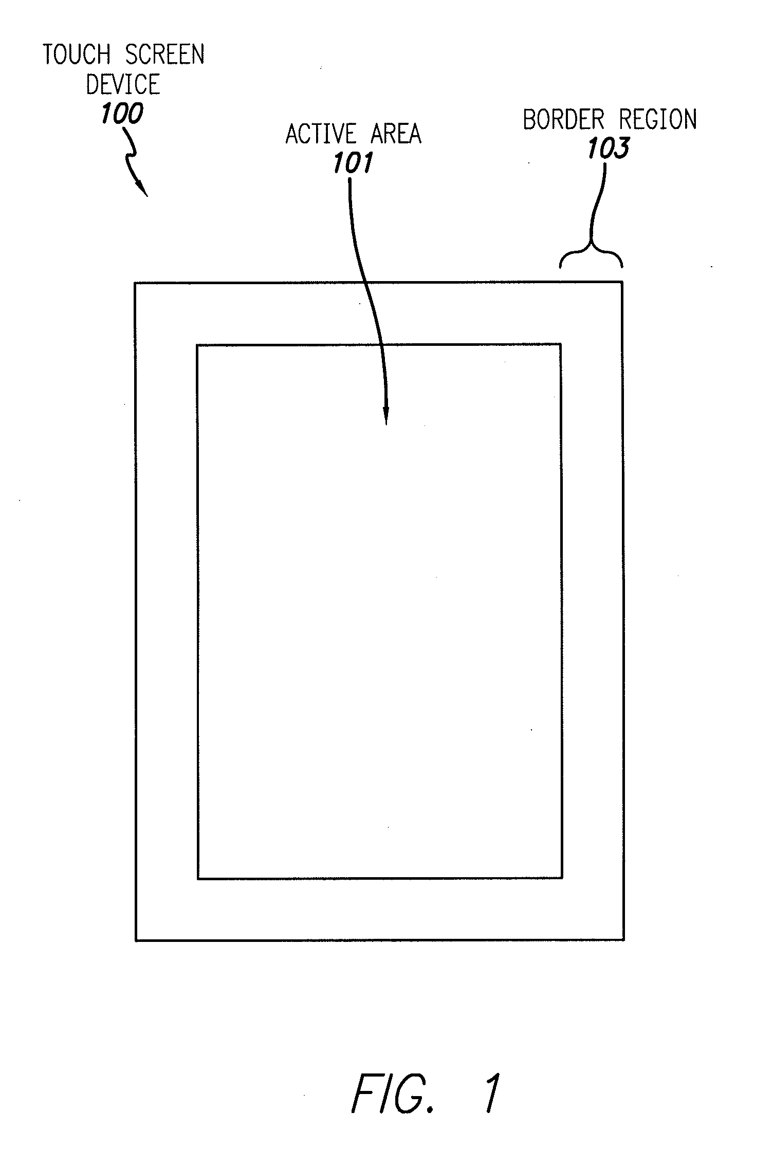
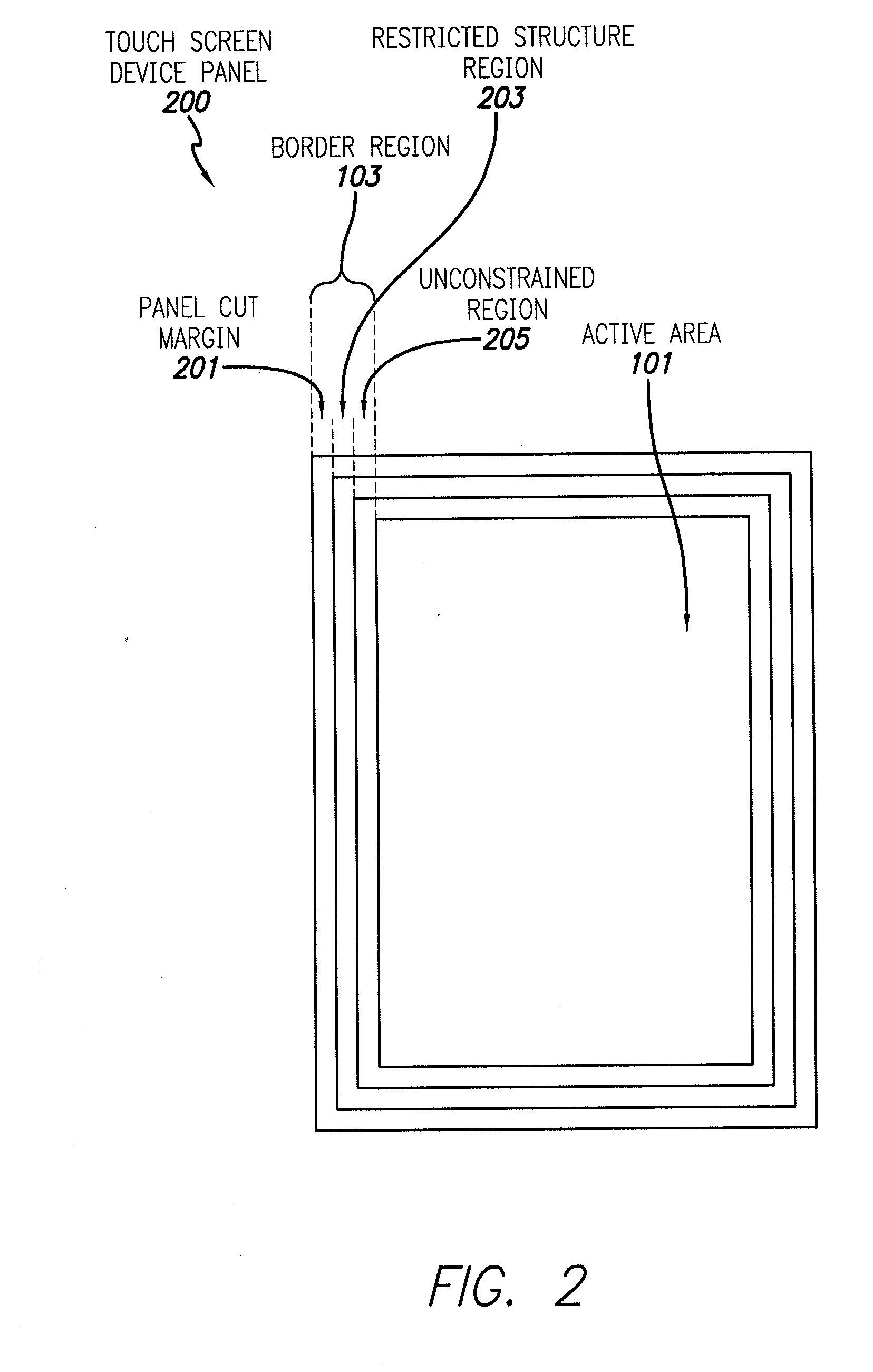
[0033]This relates to border regions of touch screens, and in particular, to compacting elements of the touch sensing and display systems in border regions more efficiently. Various embodiments described below disclose arrangements of touch sensing system circuit elements, such as common voltage lines, and display system circuit elements, such as gate drivers and gate lines, that can utilize different regions of touch screen borders in different ways. Some of the potential advantages of various embodiments can include slimmer, more compact border regions and lighter weight. Various embodiments described below include strategies that can help ...


PUM


Abstract

Touch screens with more compact border regions can include an active area that includes touch sensing circuitry including drive lines, and a border region around the active area. The border region can include an area of sealant deposited on conductive lines, and transistor circuitry, such as gate drivers, between the active area and the sealant. The conductive lines can extend from the sealant to the active area without electrically connecting to the transistor circuitry. The conductive lines can have equal impedances and can connect the drive lines to a touch controller off of the touch screen. A set of drive signal characteristics for the drive lines can be obtained by determining a transfer function associated with each drive line, obtaining an inverse of each transfer function, and applying a set of individual sense signal characteristics to the inverse transfer functions to obtain the corresponding set of drive signal characteristics.

Description

CROSS REFERENCE TO RELATED APPLICATIONS[0001]This application claims benefit of U.S. Provisional Application No. 61 / 247,524, filed Sep. 30, 2009, the contents of which are incorporated by reference herein in their entirety for all purposes.FIELD [0002]This relates to border regions of touch screens and other touch sensing devices.BACKGROUND[0003]Many types of input devices are available for performing operations in a computing system, such as buttons or keys, mice, trackballs, touch sensor panels, joysticks, touch pads, touch screens, and the like. Touch screens, in particular, are becoming increasingly popular because of their ease and versatility of operation as well as their declining price. Touch screens can include a touch sensor panel, which can be a clear panel with a touch sensitive surface, and a display device such as a liquid crystal display (LCD) that can be positioned behind the panel so that the touch sensitive surface can substantially cover the viewable area of the d...

Claims


Application Information

Patent Timeline
IPC IPC(8): G06F3/041H01J9/00
CPCG06F3/0412G06F3/041G06F3/04164G06F3/04166G06F3/0446G02F1/13338G02F1/136286G06F1/16G06F2203/04112G09G3/3677
Inventor YOUSEFPOR, MARDUKEHOTELLING, STEVEN PORTERWHITE, KEVIN J.CHANG, SHIH CHANG
Owner APPLE INC
Why Eureka
Try Eureka