
Rigid-flexible circuit board and method of manufacturing the same

Inactive Publication Date: 2011-03-31
SAMSUNG ELECTRO MECHANICS CO LTD
View PDF21 Cites 23 Cited by
  • Summary
  • Abstract
  • Description
  • Claims
  • Application Information

AI Technical Summary

Benefits of technology

[0016]Also the present invention is intended to provide a rigid-flexible circuit board which uses a metal substrate thus improving heat dissipation properties and increasing the degree of freedom with which a product may be designed, and also to provide a method of manufacturing the same.

Problems solved by technology

However, operation of the electronic part generates heat which undesirably deteriorates performance of the electronic part.
However, the conventional heat dissipating circuit board is problematic in that heat generated from the heating device 14 is transferred to the heat-weak device 15 formed on the insulating layer 12 through the insulating layer 12 and the metal core 11.
Furthermore, in the case where heat is very high, destruction of the heat-weak device 15 may be caused, undesirably reducing the total reliability of the product.
Moreover, the use of the metal substrate undesirably lowers the degree of freedom with which the product may be designed.

Method used


Image

  • Rigid-flexible circuit board and method of manufacturing the same
  • Rigid-flexible circuit board and method of manufacturing the same
  • Rigid-flexible circuit board and method of manufacturing the same

Examples


first embodiment

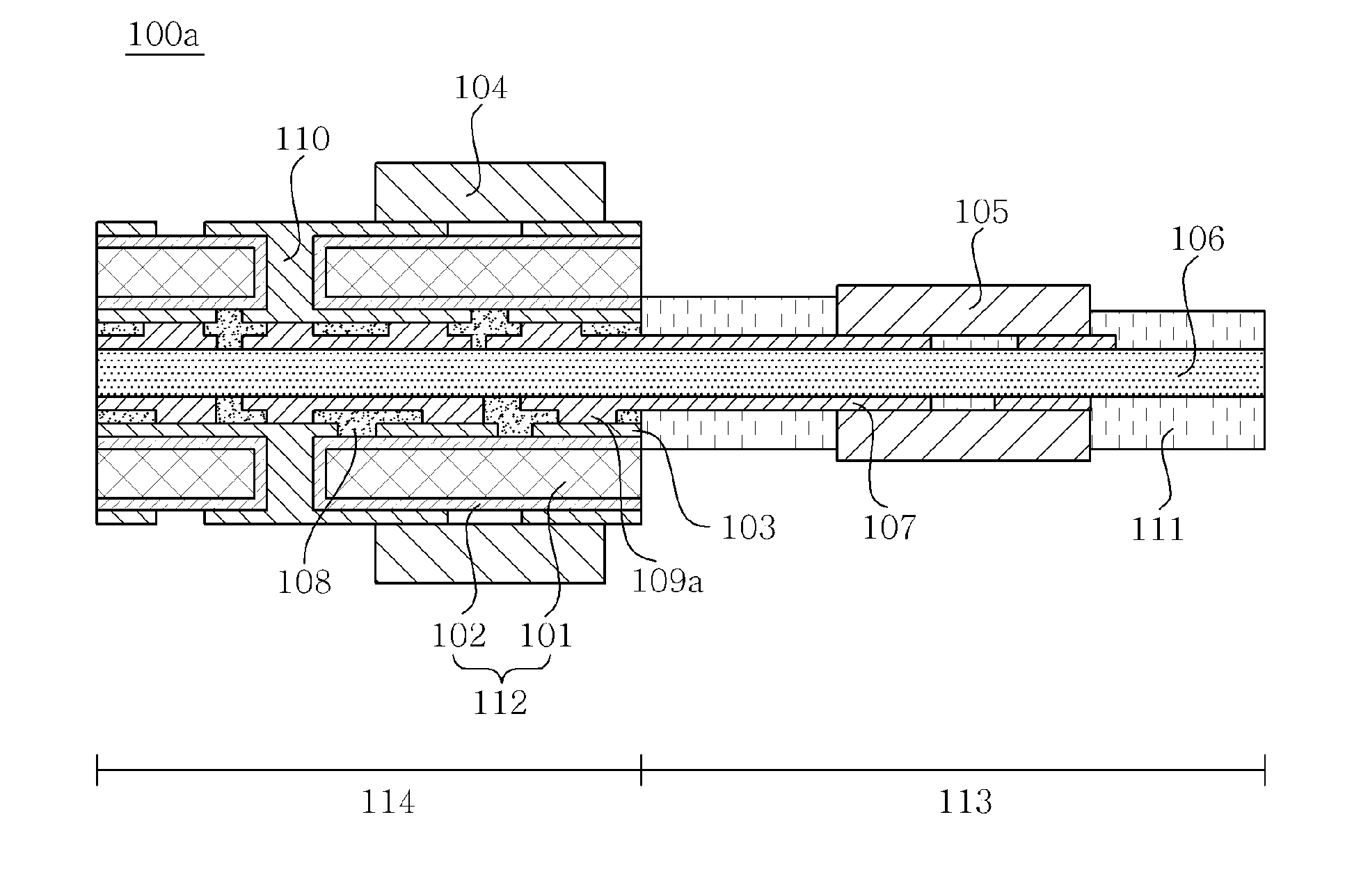
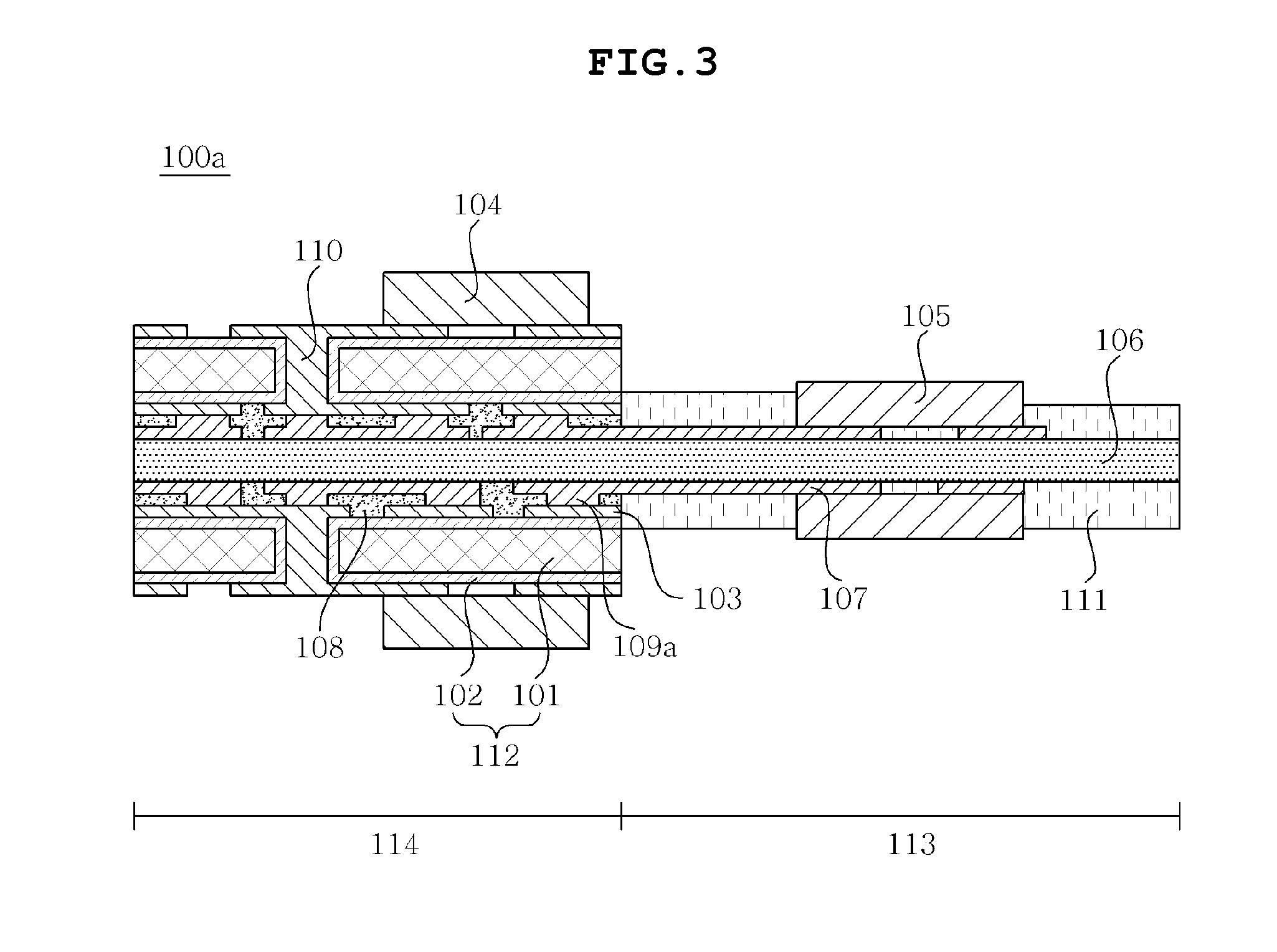
[0044]FIG. 3 is a cross-sectional view showing a rigid-flexible circuit board 100a according to the present invention. With reference to this drawing, the rigid-flexible circuit board 100a according to the present embodiment is described below.

[0045]As shown in FIG. 3, the rigid-flexible circuit board 100a according to the present embodiment generally includes a rigid region 114 and a flexible region 113, thus exhibiting thermal separation effects.

[0046]Specifically, the flexible region 113 includes a flexible substrate 106 having a first circuit layer 107 formed thereon.

[0047]The flexible substrate 106 has the functionality of an insulating material and manifests excellent flexibility, and thus increases the degree of freedom of the design of the flexible region 113. An example of a material used for the flexible substrate 106 may include but is not limited to polyimide. Any material may be used as long as it is an insulating material having high flexibility.

[0048]The rigid region ...

second embodiment

[0058]FIG. 4 is a cross-sectional view showing a rigid-flexible circuit board 100b according to the present invention. With reference to this drawing, the rigid-flexible circuit board 100b according to the present embodiment is described below. In the description of the present embodiment, elements which are the same as or similar to those of the previous embodiment are designated by the same reference numerals, and redundant descriptions thereof are omitted.

[0059]As shown in FIG. 4, the rigid-flexible circuit board 100b according to the present embodiment includes a rigid region 114 and a flexible region 113 as in the first embodiment, with the exception that a heating device 104 is disposed on one surface of the rigid region 114 and a heat-weak device 105 is disposed on the other surface of the rigid region 114. Specifically, the heating device 104 is disposed on a metal core substrate 112 having a second circuit layer 103 bonded to one surface of the rigid region 114, and the hea...


PUM

PropertyMeasurementUnit
Flexibilityaaaaaaaaaa
Stiffnessaaaaaaaaaa
Heataaaaaaaaaa

Abstract

Disclosed is a rigid-flexible circuit board, which includes a rigid region and a flexible region, the rigid region including a flexible substrate having a first circuit layer on both surfaces thereof, a metal core substrate formed on the flexible substrate and having a second circuit layer on both surfaces thereof, and an adhesive layer disposed between the flexible substrate and the metal core substrate, wherein the metal core substrate includes a metal core having a through hole, and an insulating layer formed on a surface of the metal core, so that the rigid region and the flexible region are thermally separated from each other and heat dissipation properties of the rigid region are improved. A method of manufacturing the rigid-flexible circuit board is also provided.

Description

CROSS REFERENCE TO RELATED APPLICATION[0001]This application claims the benefit of Korean Patent Application No. 10-2009-0091198, filed Sep. 25, 2009, entitled “A rigid-flexible circuit board and a method of manufacturing the same”, which is hereby incorporated by reference in its entirety into this application.BACKGROUND OF THE INVENTION[0002]1. Technical Field[0003]The present invention relates to a rigid-flexible circuit board and a method of manufacturing the same.[0004]2. Description of the Related Art[0005]Alongside the recent advancement of the electronics industry is a drastically increasing demand for electronic parts with increased functionality. Circuit boards which mount electronic parts which are lightweight, slim, short and small should be able to integrate many electronic products on the small area thereof.[0006]However, operation of the electronic part generates heat which undesirably deteriorates performance of the electronic part. Thus, circuit boards having improv...

Claims


Application Information

Patent Timeline
IPC IPC(8): H05K7/20H05K1/00H05K3/10
CPCH05K1/0203H05K1/053H05K1/189H05K3/462H05K3/4641Y10T29/49126H05K2203/0315Y10T29/49155Y10T29/49165Y10T29/49124H05K3/4691H05K1/02H05K3/46
Inventor KANG, JUNG EUNCHOI, SEOG MOONKIM, TAE HOONLEE, YOUNG KISHIN, HYE SOOKLIM, CHANG HYUN
Owner SAMSUNG ELECTRO MECHANICS CO LTD
Features
  • Generate Ideas
  • Intellectual Property
  • Life Sciences
  • Materials
  • Tech Scout
  • Unparalleled Data Quality
  • Higher Quality Content
  • 60% Fewer Hallucinations
Learn More