
Systems and methods of assembling a rotor blade extension for use in a wind turbine

a technology of rotor blades and wind turbines, which is applied in the direction of wind turbines with parallel air flow, wind energy generation, airflow influencers, etc., can solve the problems of increasing the noise generated by the turbine, increasing the surface area of the blade, and increasing the pressure fluctuations

Inactive Publication Date: 2011-03-31
GENERAL ELECTRIC CO
View PDF25 Cites 43 Cited by
  • Summary
  • Abstract
  • Description
  • Claims
  • Application Information

AI Technical Summary

Benefits of technology

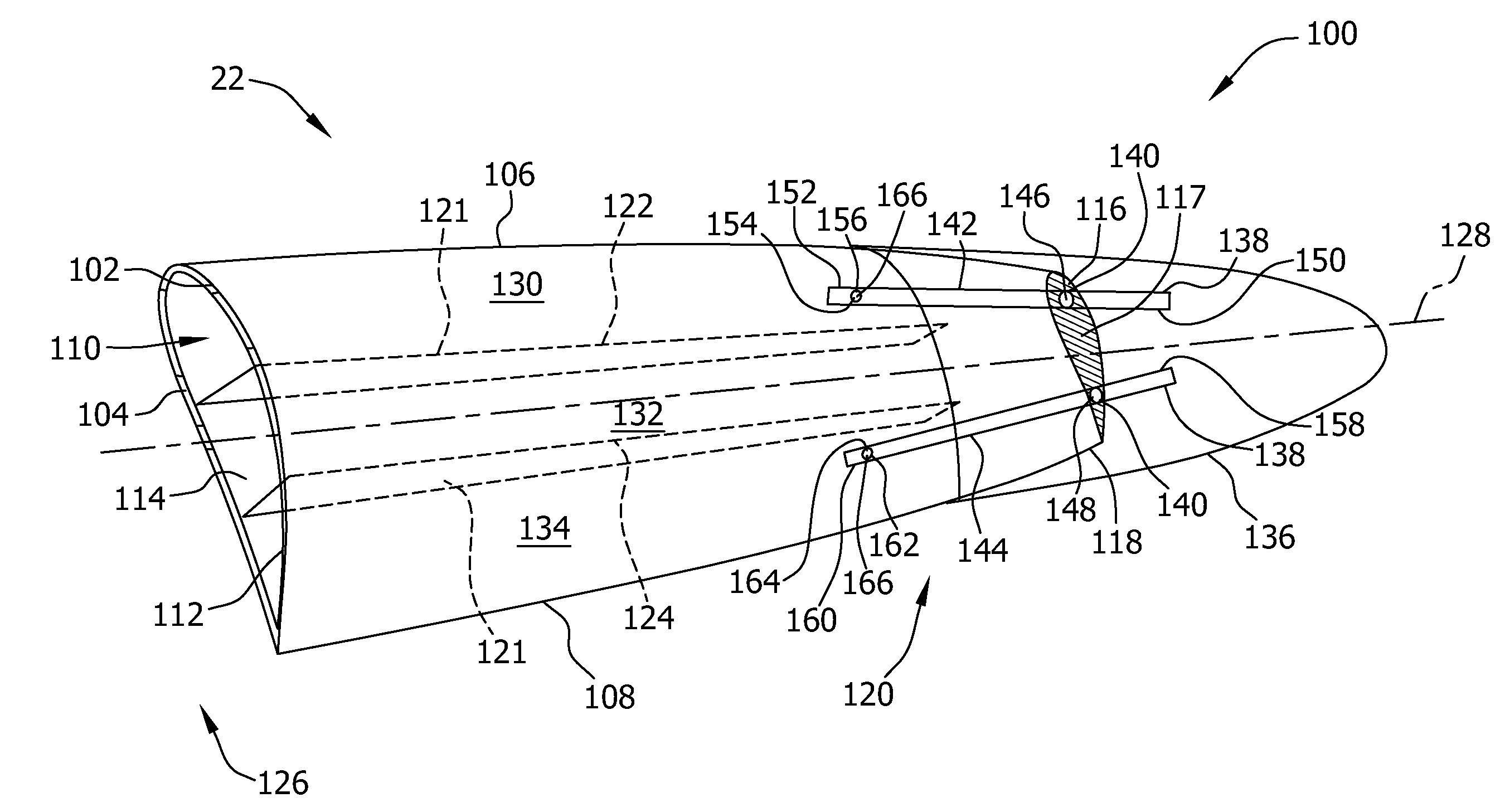
[0009]The embodiments described herein facilitate reducing noise generated at the tip portion of a rotor blade by the rotation of the rotor blade, and facilitate increasing the electrical power produced by a wind turbine. More specifically, the blade extension assembly described herein enables an increase in a length and blade surface area of an existing rotor blade, thereby facilitating an increase in the energy generated in a wind turbine. In addition, the blade extension assembly described herein facilitates modifying the vortices that trail from the rotor blade, thereby facilitating reduced levels of vortex turbulent kinetic energy (TKE), and facilitating reduced pressure fluctuations across the rotor blade surface that generate noise.

Problems solved by technology

However, blades with increased loading also tend to have a greater surface area at the blade tip, which may contribute to stronger vortices being generated at the blade tip.
The increased strength of the vortices and the interaction of each vortex with the blade surface can increase the noise generated by the turbine.
Additionally, turbulent kinetic energy (TKE) at the blade tip increases pressure fluctuations that are responsible for noise generation.
Moreover, when the flow of air separates from the blade tip, the blade surface area is “washed” by the resulting vortices, thereby generating additional noise.

Method used


Image

  • Systems and methods of assembling a rotor blade extension for use in a wind turbine
  • Systems and methods of assembling a rotor blade extension for use in a wind turbine
  • Systems and methods of assembling a rotor blade extension for use in a wind turbine

Examples


Embodiment Construction

[0018]The embodiments described herein include a wind turbine system that enables an increase in wind turbine power production and a reduction in the generation of acoustic noise during operation of the wind turbine. The systems and methods described herein facilitate retrofitting an existing rotor blade to increase a length and surface area of the rotor blade. More specifically, the blade extension assembly described herein enables an existing rotor blade to be modified to facilitate reducing noise generated at the tip portion of a rotor blade by the rotation of the rotor blade, and facilitate increasing the electrical power produced by a wind turbine.

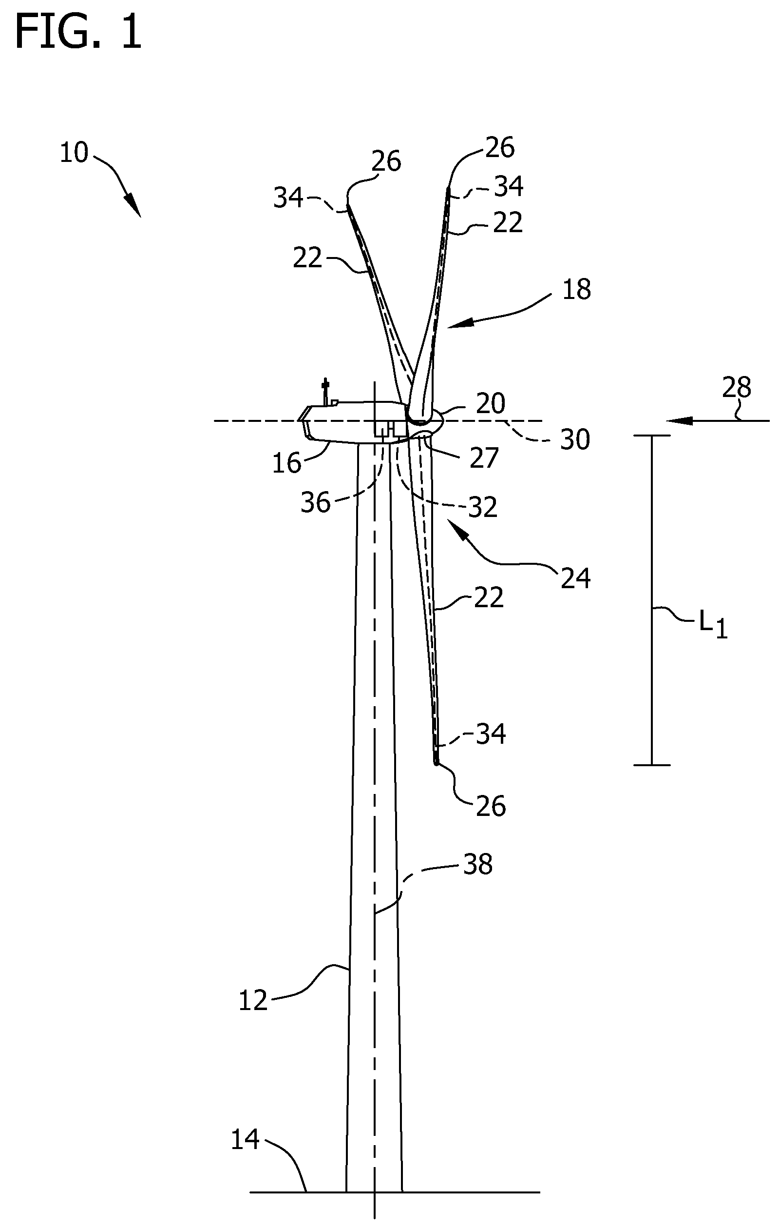
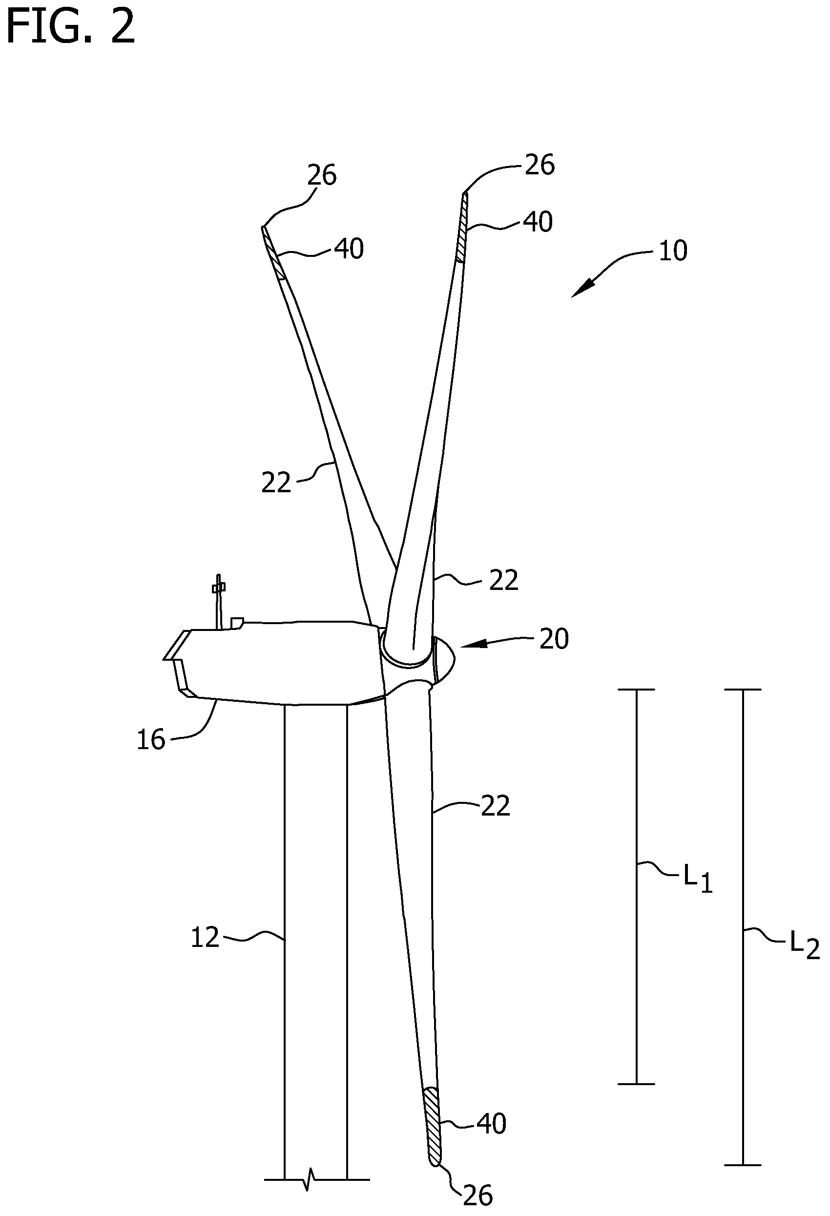
[0019]FIG. 1 is a perspective view of an exemplary wind turbine 10. FIG. 2 is an enlarged perspective view of an exemplary wind turbine 10. Components shown in FIG. 1 are labeled with similar reference numbers in FIG. 2. In the exemplary embodiment, wind turbine 10 is a horizontal-axis wind turbine. Alternatively, wind turbine 10 may ...


PUM


Abstract

A method of assembling a blade extension assembly for use with a wind turbine. The method includes removing a tip end of a tip portion of a rotor blade and coupling a tip wall to the tip portion. The tip wall extends between a first sidewall and a second sidewall and includes a plurality of slots defined therein. A blade extension assembly is coupled to the tip portion.

Description

BACKGROUND OF THE INVENTION[0001]The embodiments described herein relate generally to methods and systems for assembling a wind turbine including a blade extension, and more particularly, to systems and methods for assembling a blade extension assembly for use in a wind turbine.[0002]At least some known wind turbine towers include a nacelle fixed atop a tower, wherein the nacelle includes a rotor coupled to a generator through a shaft. In known rotor assemblies, a plurality of blades extend from the rotor. The blades are oriented such that wind passing over the blades turns the rotor and rotates the shaft, thereby driving the generator to generate electricity.[0003]As air passes over each blade, a pressure differential results on opposing sides of the blade, such that a higher pressure is generated on one side and a lower pressure is generated on the opposite side. Because of this pressure differential, air tends to curl around the blade tip to establish pressure equilibrium. The ge...

Claims


Application Information

Patent Timeline
IPC IPC(8): F03D11/00B23P15/04
CPCF03D1/0675F03D1/0683Y02E10/721F05B2230/80Y10T29/49318F05B2260/96Y10T29/49336Y10T29/49337F05B2240/302Y02E10/72Y02P70/50F05B2240/307
Inventor SANTIAGO, PEDRO LUIS BENITOSEGOVIA, EUGENIO YEGRO
Owner GENERAL ELECTRIC CO
Learn More