Optical probe and endoscope apparatus

an endoscope and optical probe technology, applied in the field of optical probes and endoscopes, can solve the problems of not being able to observe the cross section not being able to dispose of optical components, and not being able to observe the image of the distal end portion

Inactive Publication Date: 2011-03-31
FUJIFILM CORP
View PDF2 Cites 19 Cited by
  • Summary
  • Abstract
  • Description
  • Claims
  • Application Information

AI Technical Summary

Benefits of technology

As described above, according to the first invention there are the advantages that it is possible to advance a probe along a guidewire as far as an affected area, and by pulling back the guidewire to a handle portion and pushing out the imaging core to the distal end portion, it is possible to perform observation of a distal part and obtain an image without any guidewire artifacts.
Further, according to the second invention, there is the advantage that it is possible to advance a probe along a guidewire to an affected area, and obtain a tomographic image of a wide area without any guidewire artifacts.

Problems solved by technology

However, although Japanese Patent No. 4021975 discloses arranging a guidewire lumen at a front portion of an imaging core lumen, since the guidewire lumen is present at the front of the imaging core lumen, it is not possible to observe a cross section of the distal end portion.
More specifically, when a guidewire lumen is provided at the front of the imaging core lumen as shown in FIG. 19, it is not possible to dispose an optical member at the distal end of the probe, and thus an image of a distal end portion can not be observed.
Moreover, with the configuration described in Japanese Patent No. 4021975, there is the problem that guidewire artifacts are visualized in images at the time of observation, and it is also not possible to observe tissue that is at the rear of the guidewire.
However, when applying this technology to an optical probe, since the distal end portion of the imaging core lumen is open, a normal image cannot be obtained due to the entry of blood or body fluids or the like to the imaging core lumen.
More specifically, when a technique that combines a guidewire lumen and an imaging core lumen at a distal end portion as in the ultrasound probe described in Japanese Patent No. 3367666 is applied to an optical probe, as shown in FIG. 20 and FIG. 21, the distal end portion of the imaging core lumen is open and consequently blood or body fluids enter into the imaging core portion and a normal image cannot be obtained.
Hence, practical implementation of this technique is not possible.

Method used


Image

  • Optical probe and endoscope apparatus
  • Optical probe and endoscope apparatus
  • Optical probe and endoscope apparatus

Examples


first embodiment

First, an embodiment (first embodiment) relating to the first invention is described.

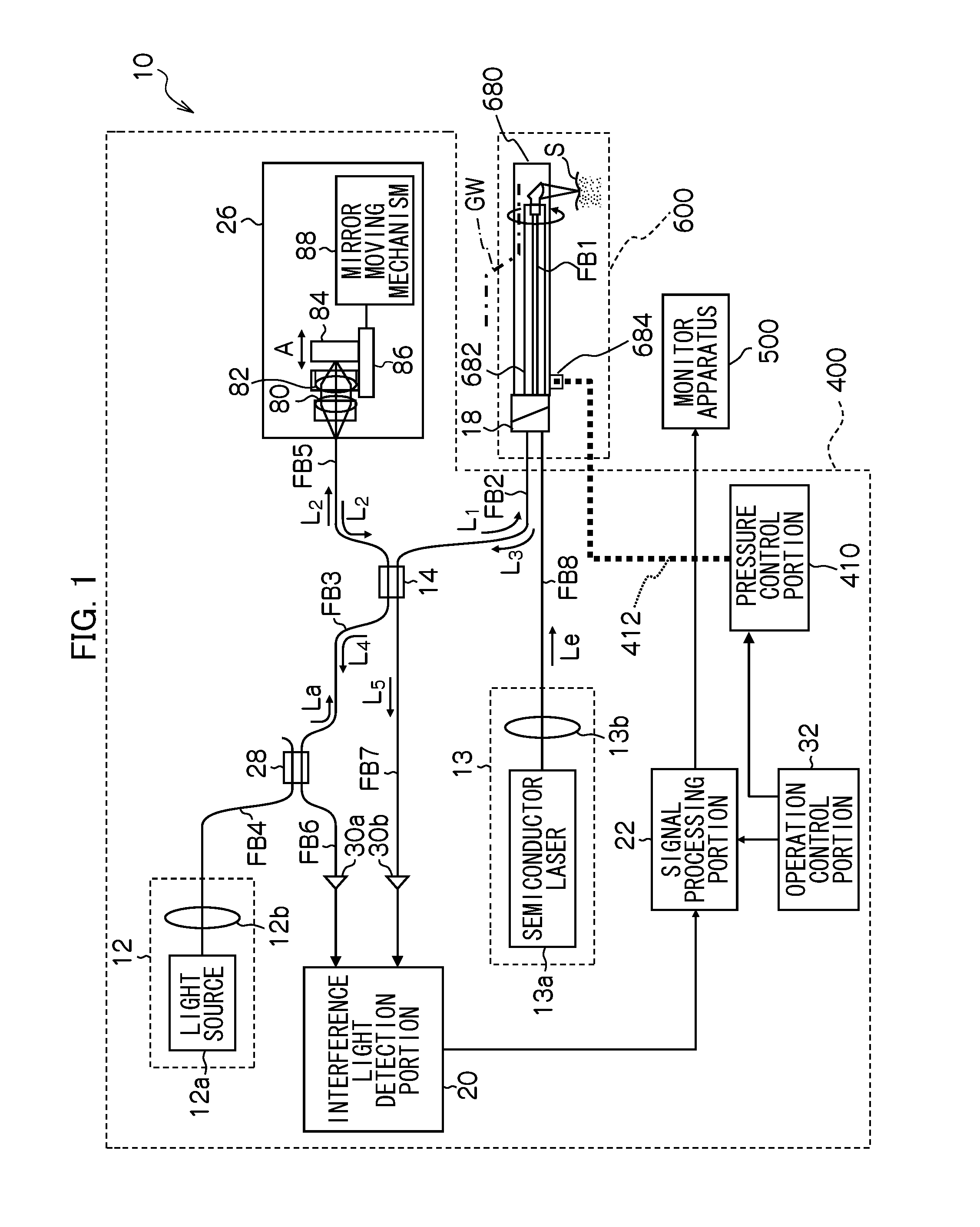
As shown in FIG. 1, an OCT probe 600 and an OCT processor 400 of the present embodiment are used for acquiring an optical tomographic image of an object to be measured by using the optical coherence tomography (OCT) technique.

[OCT Processor]

The OCT processor 400 includes a first light source (a first light source unit) 12 that emits a light La for measurement; an optical fiber coupler (a branching / multiplexing portion) 14 that branches the light La emitted from the first light source 12 into a measurement light (a first light flux) L1 and a reference light L2, and multiplexes a returning light L3 from an object to be measured S as a subject and the reference light L2, thereby generating an interference light L4; the OCT probe 600 including a rotation-side optical fiber FB1 that guides the measurement light L1 that is branched at the optical fiber coupler 14 to the object to be measured and guides th...

second embodiment

Next, an embodiment (second embodiment) relating to a second invention is described. Hereunder, a description regarding portions that are common with the first embodiment is omitted, and the description centers on characteristic portions of the present embodiment.

FIG. 8 is a sectional view that illustrates the sheath portion of the OCT probe according to the second embodiment. In this connection, in FIG. 8 and FIGS. 9 to 16 that are described later, components that are the same as or similar to components of the first embodiment (FIG. 3 to FIG. 5) are designated by the same reference numerals.

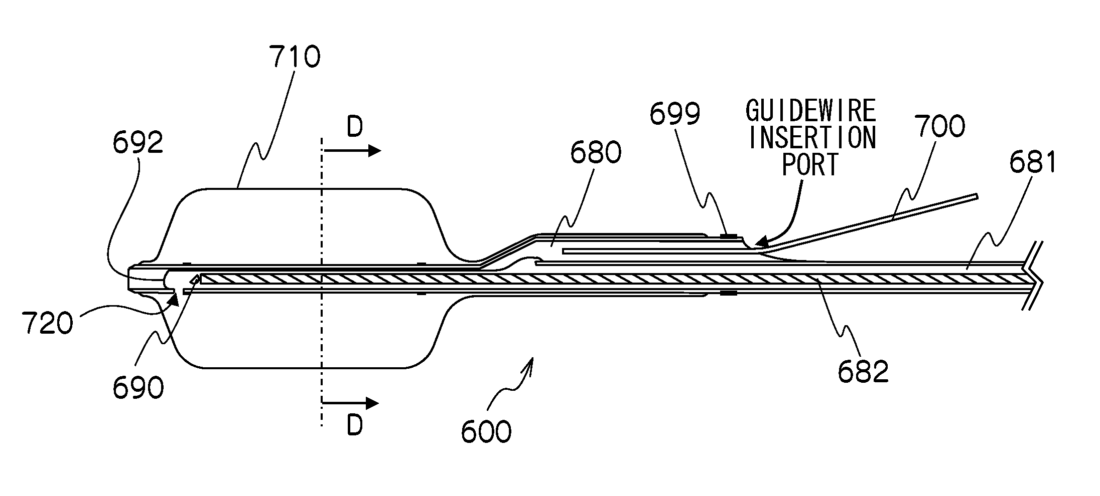
The sheath portion of the OCT probe 600 is a principal component according to the second embodiment. As shown in FIG. 8, the sheath portion of the OCT probe 600 according to the second embodiment includes the imaging core lumen 681 that houses the imaging core therein (extending) along the longitudinal axis of the sheath portion of the OCT probe 600, the guidewire lumen 680 that is disposed app...

modification example 1

FIG. 14 is a cross-sectional schematic diagram of modification example 1 of the present embodiment. Modification example 1 illustrates a difference from the present embodiment. When the balloon 710 illustrated in the present embodiment is expanded at a fragile lesion part, there is a risk of damaging the lesion part. Therefore, according to modification example 1, a configuration is adopted such that a diameter φX at both ends of the balloon 710 is greater than a diameter φY at a center part thereof (φX>φY; for example, X=10 mm and Y=12 mm), a distance from the observation target is secured with the diameter φX at both ends of the balloon 710, and an area scanned by the ball lens 690 (axial direction scanning area) does not closely contact a lesion.


PUM


Abstract

According to the optical probe of an aspect of the present invention, the flexible and optically transparent partition wall separates the imaging core lumen and the guidewire lumen, and the pressure increasing/decreasing port increases/decreases the pressure inside the imaging core lumen that is at a proximal part of the imaging core lumen. It is therefore possible to advance the probe along the guidewire as far as an affected area, and by pulling back the guidewire to a handle portion to push out the imaging core to the distal end portion, it is possible to observe a distal part and obtain an image without guidewire artifacts.

Description

BACKGROUND OF THE INVENTION1. Field of the InventionThe present invention relates to an optical probe and an endoscope apparatus that acquire an optical coherence tomographic image inside a body cavity, and more particularly to an optical probe and an endoscope apparatus that have a guidewire lumen through which a guidewire that aids insertion into a body cavity can be passed.2. Description of the Related ArtDiagnostic imaging in which an optical probe is inserted into a body cavity such as a blood vessel, bile duct, pancreatic duct, stomach, esophagus or colon to obtain a tomographic image of a living organism by performing radial scanning is already being widely performed. As an example thereof, optical coherent tomography (OCT) is being utilized in which a probe that contains therein an optical fiber having an optical lens and an optical mirror attached at the distal end thereof is inserted into a body cavity, and light is radiated into the body cavity while radially scanning the...

Claims


Application Information

Patent Timeline
Patent Type & Authority Applications(United States)
IPC IPC(8): A61B1/07A61B1/00
CPCA61B1/00082A61B1/00096A61B1/018A61M2025/0183A61B5/0084A61B5/6852A61B5/0066
Inventor HIROTA, KAZUHIRO
Owner FUJIFILM CORP
Why Eureka
Try Eureka