
Power saw apparatus with integrated dust collector

a technology of dust collector and power saw, which is applied in the direction of metal sawing accessories, working accessories, manufacturing tools, etc., can solve the problems of uncontrolled release of airborne dust and particulate matter, environmental concerns, and additional problems such as waste water pollution, and achieve the effect of optimizing the useful surface area and reducing friction

Active Publication Date: 2011-04-07
JPL GLOBAL
View PDF36 Cites 48 Cited by
  • Summary
  • Abstract
  • Description
  • Claims
  • Application Information

AI Technical Summary

Benefits of technology

The present invention is a power saw with a blade guard and a dust collection housing. The saw has a fan that creates negative pressure to filter and collect dust from the work piece. The fan is connected to a cylindrical filter cartridge and a vacuum suction tube. The saw also has a structural arm and a retractable shroud for better control and stability when cutting the work piece. The dust collection housing has a fan housing, a vacuum suction tube, a spin handle, and a slot for receiving the structural arm. The invention also includes a blade guard with a lower portion that forms a vacuum chamber for collecting dust. The method for cutting a work piece involves rotating the drive belt, rotating the circular saw blade, covering the blade guard with a lower portion, creating negative pressure, filtering dust, and collecting dust within a dust collection bin.

Problems solved by technology

Also known, is a problem of uncontrolled release of and exposure to airborne dust and particulate matter resulting from cutting a workpiece.
In addition to health issues, the dust by-products present a clean-up challenge, even if all individuals in a contained environment have donned respirators.
While most wet cutting methods work relatively well, they create additional problems of waste water pollution and environmental concerns.
One problem with these and other numerous examples is that an external bag is required to collect dust that reduces the portability of the apparatus.
Another problem in the prior art is that dusty air is sucked through the fan continually that increases wear on the moving components.

Method used


Image

  • Power saw apparatus with integrated dust collector
  • Power saw apparatus with integrated dust collector
  • Power saw apparatus with integrated dust collector

Examples


Embodiment Construction

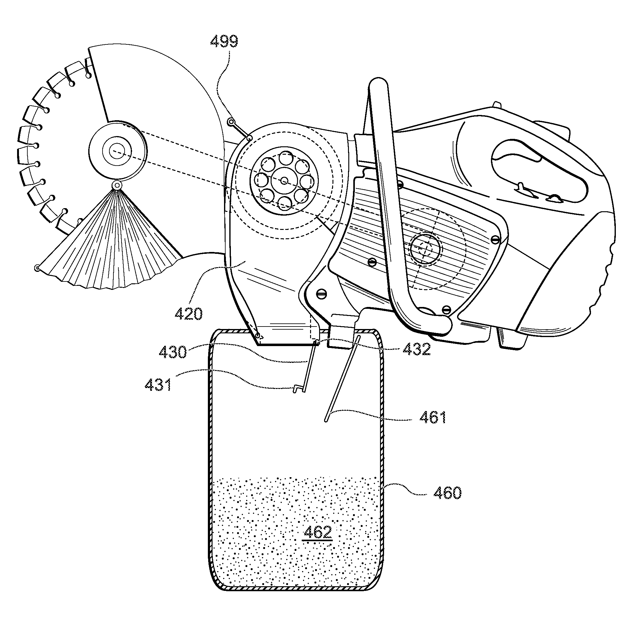
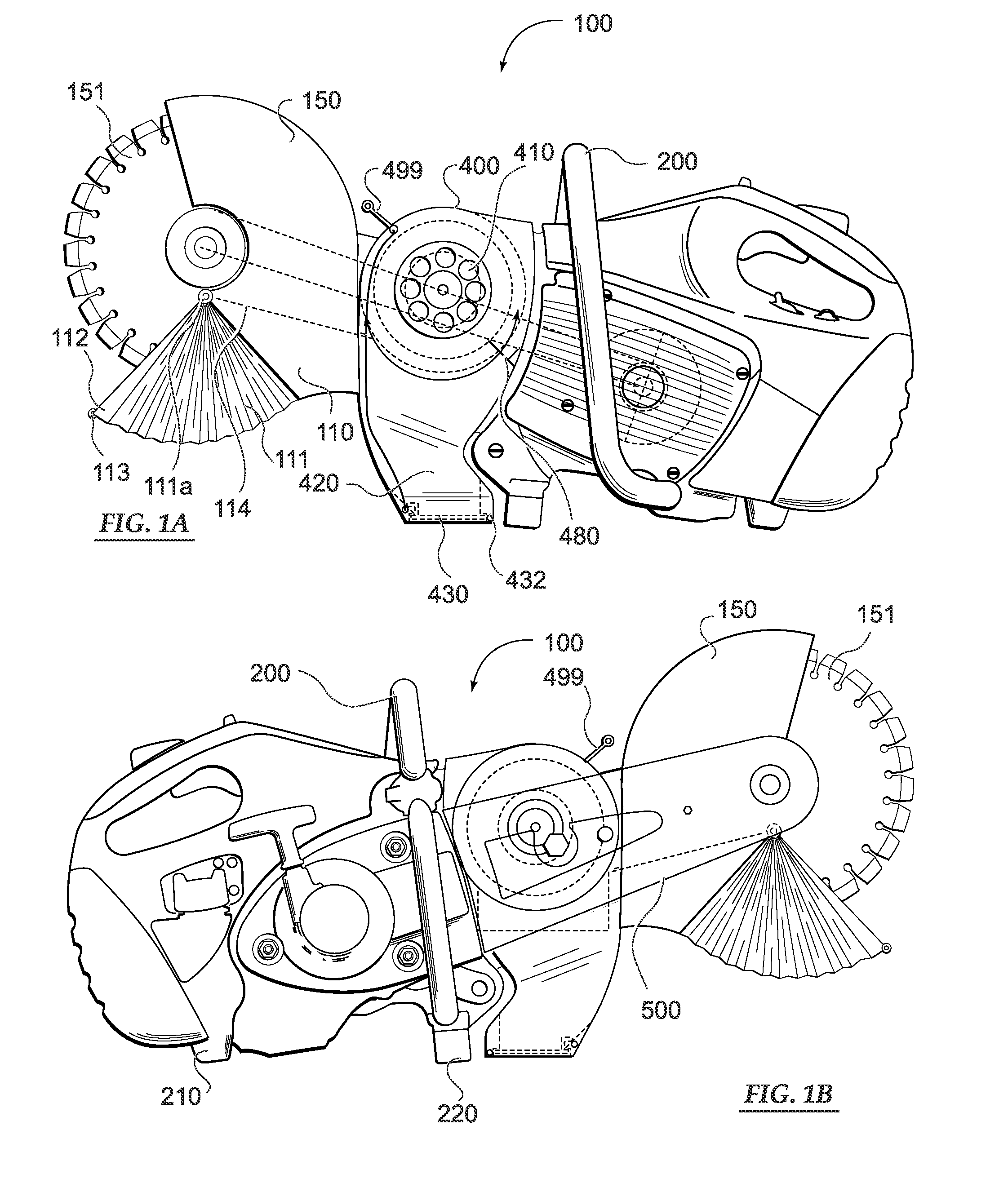
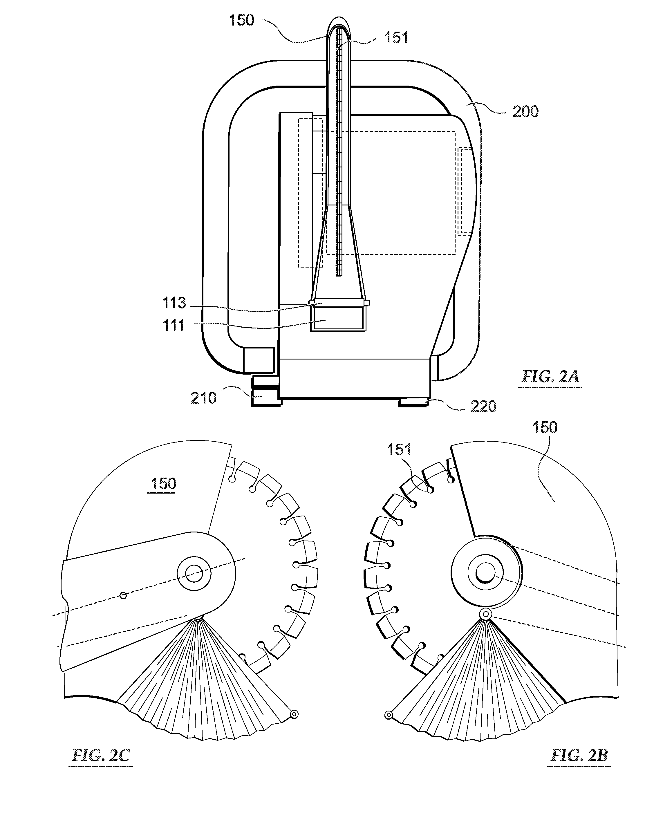
[0037]Referring initially to FIG. 1A, a left side profile view of a power saw according to the present invention is illustrated. The preferred embodiment 100 comprises a portable hand-held saw which is configured to cut metal, plastic or masonry. More specifically, masonry comprises stone, concrete, brick, and other materials. The power saw and dust collection system 100 is powered by a motor in the after part of the saw. The working end comprises a rotating blade 151 protected by a blade guard 150 having upper and lower portions. Importantly, the lower blade guard forms a vacuum channel 110 for dust and particulate to flow initiating dust containment. Additionally, the lower blade guard comprises an adjustable, retractable shroud 111 about a pivot point 111a. A leading edge of the shroud 111 has a ridged jaw 112 while the shroud 111 may be made from bendable material. Further, the bottom most portion of the ridged jaw 112 comprises a roller 113 to assist in alignment with moving al...


PUM

PropertyMeasurementUnit
pressureaaaaaaaaaa
tensionaaaaaaaaaa
surface areaaaaaaaaaaa

Abstract

A power saw having a circular saw blade or, grinding wheel incorporated to a dust collection system that is easily portable is disclosed herein. In a preferred embodiment, negative pressure and resulting air flow is provided at a lower blade guard to capture particulate matter as a byproduct of cutting a work piece. A unique dust collection housing is additionally provided having a filter to remove dust from air and exhaust the filtered air at a lateral side of the saw. A spin handle is additionally disclosed to increase the usable surface of the filter and to work in conjunction with a filter cleaning flap. A drive belt according to a preferred embodiment, drives the circular saw and a vacuum fan. Among the beneficial aspects of the power saw is its portability by obviating a need for a dust collection bag and / or a separate vacuum unit.

Description

BACKGROUND OF THE INVENTION[0001]1. Field of the Invention[0002]The present invention pertains generally to power masonry tools and related devices for cutting and grinding. More specifically, the present invention relates to portable type power saws driven by an internal combustion engine or electric motor and having dust abatement while cutting cinder block, concrete, brick, clay, stone, tile, and the like.[0003]2. Description of the Prior Art[0004]Circular saws using a rotating circular saw blade have been known for some time. Early versions include those employed by saw mills to make lumber. Hand-held circular saws have also been known for many decades that were first used mainly in woodworking applications. Improvements to saw blade design and material have lead to expanded applications for portable saws including masonry, plastic and even metal. Many such saws are currently powered by electric motors; however internal combustion motors may also be employed.[0005]Also known, is...

Claims


Application Information

Patent Timeline
Patent Type & Authority Applications(United States)
IPC IPC(8): B28D7/02B28D1/04B26D7/18
CPCB23D45/16B23D59/006B28D7/02B24B55/04B24B55/10B27G19/04B28D1/04Y10T83/0453
Inventor GUTH, PAUL
Owner JPL GLOBAL
Learn More