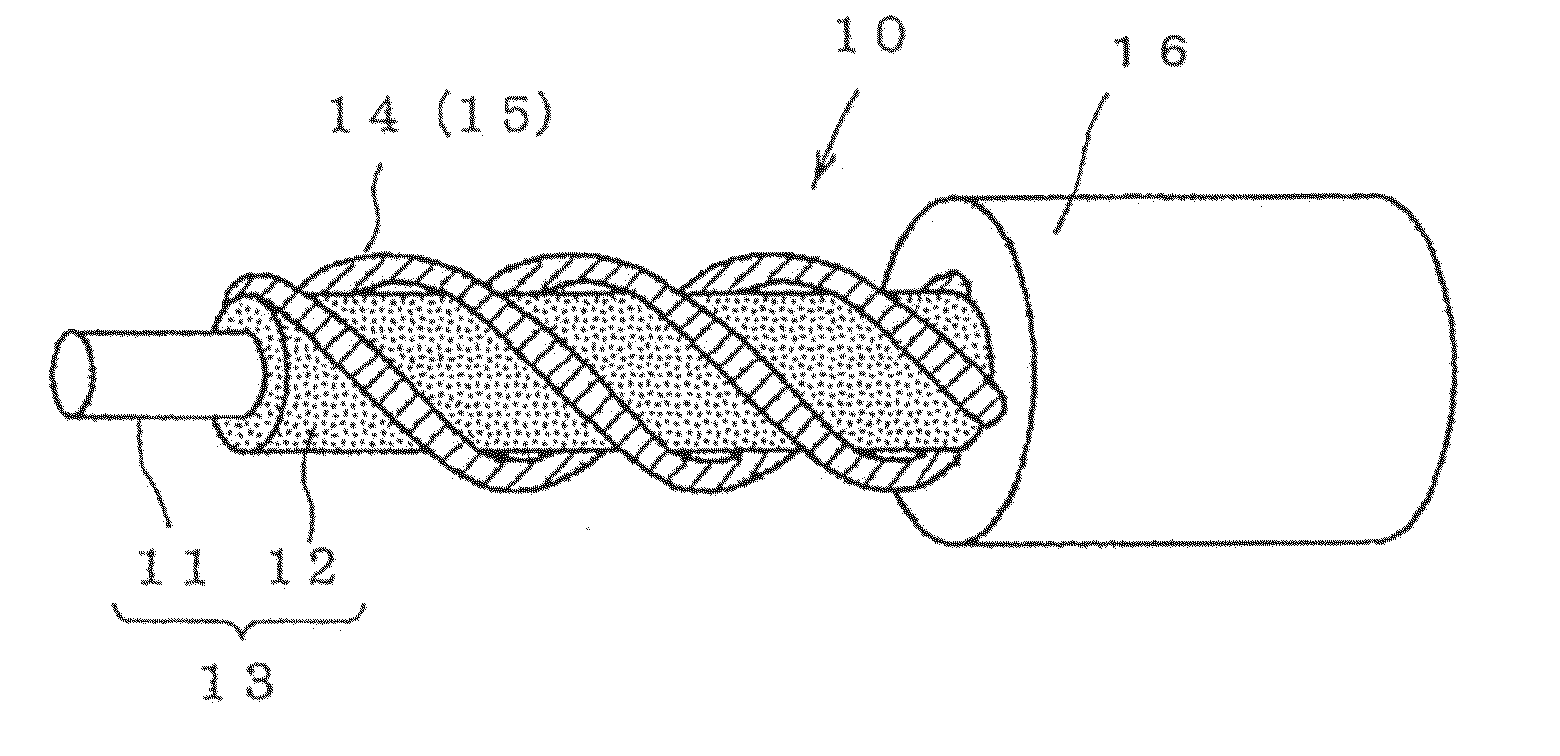
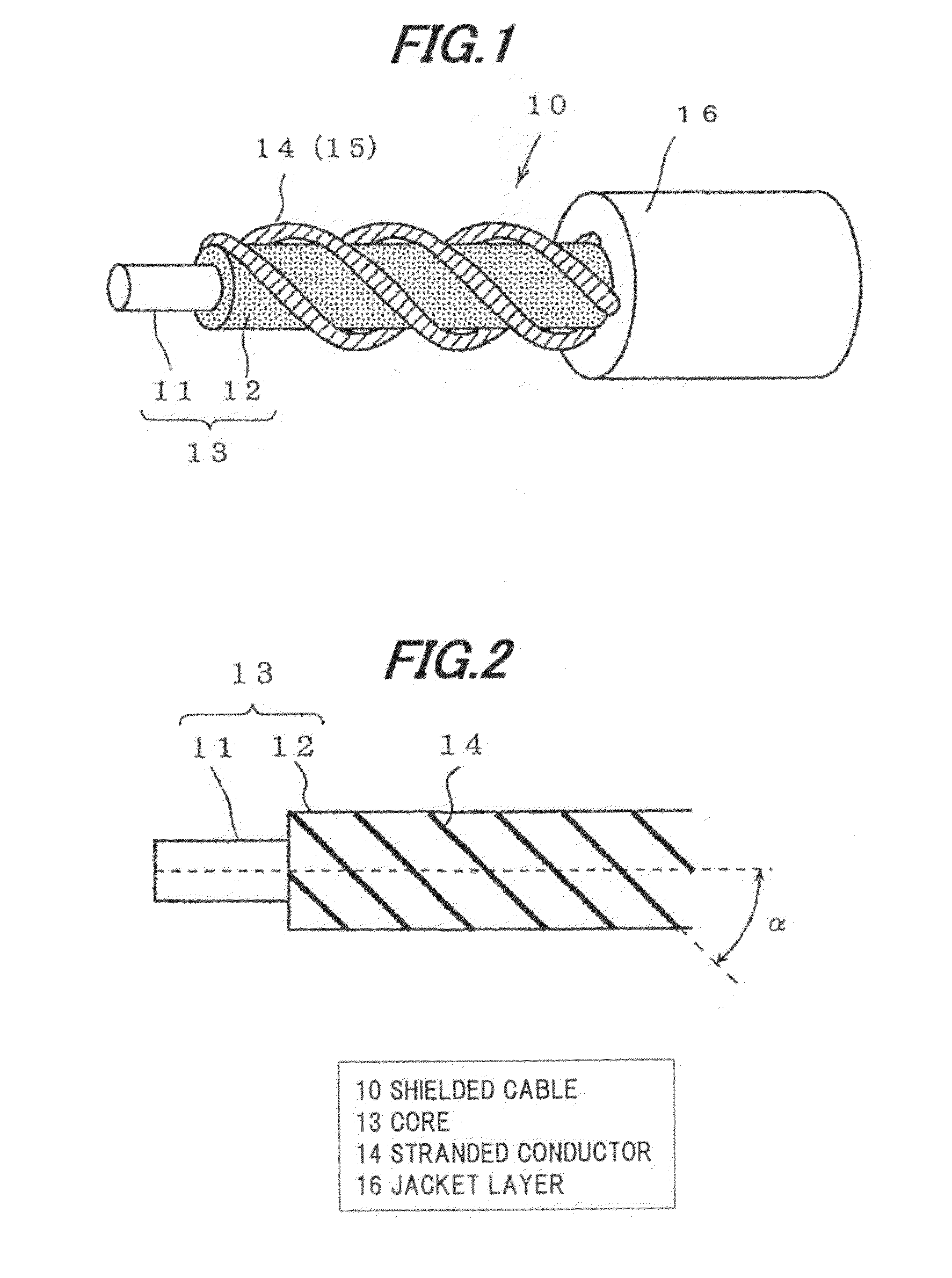
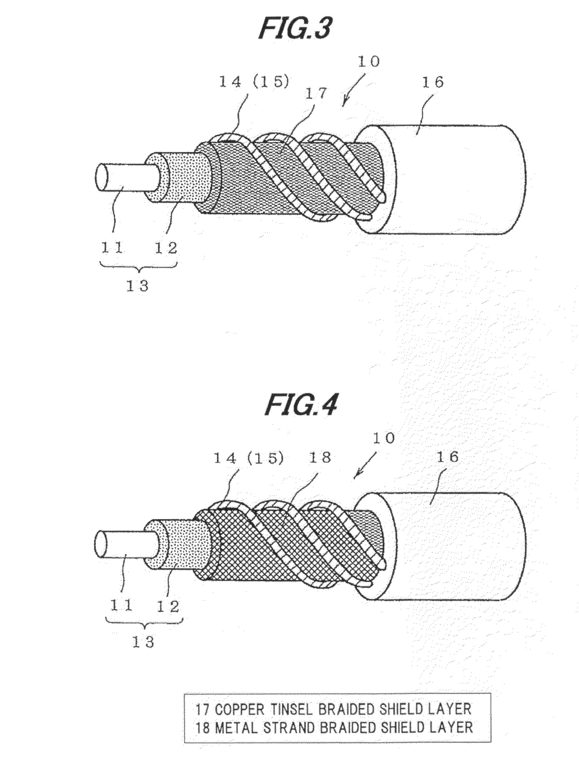
Shielded cable

a shield layer and cable technology, applied in the direction of insulated conductors, power cables, cables, etc., can solve the problems of metal wire forming shield layers likely to be disconnected by friction, metal wire forming shield layers likely to be broken, metal wires grinding, etc., to achieve excellent bending durability

Active Publication Date: 2011-04-07
HITACHI METALS LTD
View PDF17 Cites 15 Cited by
  • Summary
  • Abstract
  • Description
  • Claims
  • Application Information

AI Technical Summary

Benefits of technology

[0009]Along with the popularization of robots and use of in-vehicle electronics, a shielded cable recently has been often arranged in an environment where the cable is repeatedly and often bent or twisted, accordingly, the shield cable has been required to have excellent bending durability and torsion durability.

Problems solved by technology

First of all, the metal wire braided shielded cable has a problem that metal wires grind against each other due to bend or torsion of the shielded cable and the metal wire forming a shield layer is likely to be disconnected by friction.
Meanwhile, the metal wire served shielded cable has excellent bending durability compared with the above-mentioned metal wire braided shielded cable, but has a problem in the torsion that the metal wire forming a shield layer is likely to be disconnected in the same manner as the metal wire braided shielded cable since large strain is generated when the shielded cable is twisted.

Method used


Image

  • Shielded cable
  • Shielded cable
  • Shielded cable

Examples


example 1

[0050]A tinned soft conductor of φ 0.12 mm was used as the inner conductor 11 of the shielded cable 10 of FIG. 1 and the core 13 composed of an insulated wire was formed by coating an outer periphery of the tinned soft conductor with cross-linked polyethylene as the insulation 12. The stranded conductor 14 was formed by twisting plural tinned soft conductors of φ 0.12 mm, the stranded conductor shield layer 15 was then formed by winding four stranded conductors 14 around the outer periphery of the core 13 composed of one insulated wire at the winding angle of 30±5° with respect to the central axis of the core 13, and the outer periphery thereof was further coated with ethylene propylene diene rubber as the jacket layer 16, thereby forming the shielded cable.

example 2

[0051]The shielded cable 10 of FIG. 3 was made under the same conditions as Example 1 except that the tinsel copper braided shield layer 17 was formed by braiding plural tinsel coppers (φ0.11 mm, copper foil thickness of 12 μm) each of which is a core thread with copper foil wrapped therearound, and was arranged between the core 13 and the stranded conductor shield layer 15.

example 3

[0052]The shielded cable 10 of FIG. 4 was made under the same conditions as Example 1 except that the metal strand braided shield layer 18 was formed by braiding plural metal plated strands (φ0.12 mm) each of which is a core thread plated with metal, and was arranged between the core 13 and the stranded conductor shield layer 15.


PUM

PropertyMeasurementUnit
winding angleaaaaaaaaaa
angleaaaaaaaaaa

Abstract

A shielded cable includes a core comprising an insulated wire including an inner conductor and an insulation layer formed on an outer periphery of the inner conductor, a shield layer formed on an outer periphery of the core, and a jacket layer formed on an outer periphery of the shield layer. The shield layer includes a stranded conductor shield layer including a stranded conductor spirally wound around the core, and the stranded conductor includes a plurality of conductor strands stranded together. The shield layer may further include a tinsel copper braided shield layer or a metal plated strand braided shield layer that is formed between the core and the stranded conductor shield layer.

Description

[0001]The present application is based on Japanese Patent Application Nos. 2009-231414 and 2010-142392 filed on Oct. 5, 2009 and Jun. 23, 2010, respectively, the entire contents of which are incorporated herein by reference.BACKGROUND OF THE INVENTION[0002]1. Field of the Invention[0003]The invention relates to a shielded cable provided with a shield layer on a periphery of one or plural insulated wires, in particular, to a shielded cable excellent in bending durability and torsion durability.[0004]2. Description of the Related Art[0005]Conventionally, equipments such as electronic information equipment or household electrical appliance have a problem that an inverter, etc., placed in the equipment is a generation source of electromagnetic noise and the electromagnetic noise generated by the generation source is radiated (emitted) via a cable, resulting in adverse affect such as an improper operation, etc., on other peripheral devices.[0006]In addition, there is a problem that the e...

Claims


Application Information

Patent Timeline
Patent Type & Authority Applications(United States)
IPC IPC(8): H01B9/02
CPCH01B11/1878H01B11/1821
Inventor ESHIMA, HIROTAKA
Owner HITACHI METALS LTD
Why Eureka
Try Eureka