Method to save energy for devices with rotating or reciprocating masses

a technology of rotating or reciprocating mass and energy saving, applied in the direction of motor/generator/converter stopper, dynamo-electric converter control, ac motor direction control, etc., can solve the problems of potential turn-off time and considered a potential turn-on time, and achieve high periodic variation of the load on the motor and superior energy saving

Active Publication Date: 2011-04-07
THE POWERWISE GRP
View PDF104 Cites 35 Cited by
  • Summary
  • Abstract
  • Description
  • Claims
  • Application Information

AI Technical Summary

Benefits of technology

[0029]The system and method take advantage of the highly periodic variation of the load on the motor in a pump jack application. The system and method accurately predict those times during a pumping stroke when the power to the motor may be completely turned off, as well as the appropriate time at which the power should be reapplied. Completely turning off the power to the motor results in superior energy savings.

Problems solved by technology

This is considered a potential turn-off time.
This is considered a potential turn on time.

Method used


Image

  • Method to save energy for devices with rotating or reciprocating masses
  • Method to save energy for devices with rotating or reciprocating masses
  • Method to save energy for devices with rotating or reciprocating masses

Examples


Embodiment Construction

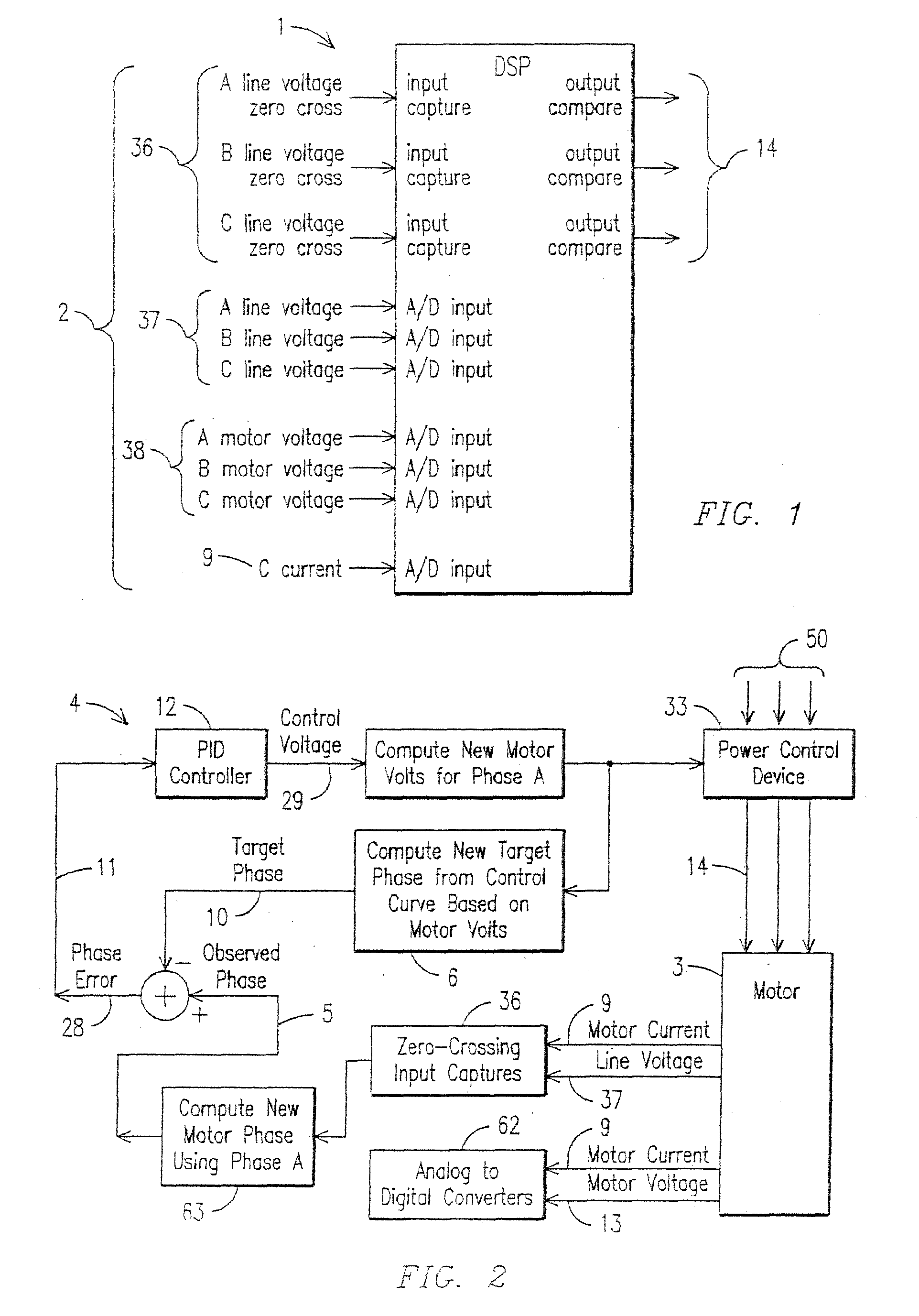
[0073]With reference to FIG. 1, a block diagram of a digital signal processor (DSP) 1 and hardware inputs and outputs is shown. The DSP 1 can observe the operational characteristics of a motor and make corrections to root mean square (RMS) voltage for the motor that is running and under closed loop control. Hardware inputs 2 capture phase zero crossing inputs 36, phase line voltage 37, phase motor voltage 38 and current 9 and passed through the DSP 1 for processing and then onto power control devices through the power control device outputs 14.

[0074]Referring now to FIG. 2, a block diagram of a system and method of the DSP-based motor controller 4 is shown. First, the motor controller 4 reads the voltages 37 of each phase A, B and C and current 9 to capture the zero-crossing inputs 36. At this point voltage 13 and current 9 may be converted from analog to digital using converters 62. Next, computations 63 of motor phase angle for each phase are calculated to yield an observed phase ...


PUM


Abstract

A system and method are disclosed for turning off the voltage to a pump jack electric motor during predetermined periods of time to save energy. In the method, the motor's response to closed-loop control may be evaluated over several pump strokes. The periods of the pump stroke when it is feasible to turn off the motor may be identified. The consistency of the measurements over several strokes may be evaluated. The motor may be turned off during predetermined periods on subsequent pump strokes when each pump stroke shows sufficiently similar behavior to that predicted during the closed-loop control process. The system may return to the closed-loop control process after a predetermined period of time to adjust to any changes in the system.

Description

CROSS-REFERENCE TO RELATED APPLICATIONS[0001]This application is a continuation-in-part of co-pending U.S. application Ser. No. 12 / 873,510 filed Sep. 1, 2010, which claims the benefit of U.S. Provisional Application No. 61 / 240,399 filed Sep. 8, 2009, all of which applications are hereby incorporated by reference for all purposes in their entirety.STATEMENT REGARDING FEDERALLY SPONSORED RESEARCH OR DEVELOPMENT[0002]N / AREFERENCE TO MICROFICHE APPENDIX[0003]N / ABACKGROUND OF THE INVENTION[0004]1. Field of the Invention[0005]This invention relates to electric motors used to operate pump jacks and other devices with rotating or reciprocating masses.[0006]2. Description of the Related Art[0007]A pump jack is an above ground driving device for a reciprocating piston pump installed downhole in an oil well. The pump jack mechanically lifts liquid out of the well when there is not enough bottom hole pressure for the liquid to flow by itself to the surface. The pump jack is often powered by an ...

Claims


Application Information

Patent Timeline
Patent Type & Authority Applications(United States)
IPC IPC(8): H02P1/04
CPCH02P6/002H02P23/0036H02P23/0072H02P6/182H02P1/04H02P23/0004H02P6/28H02P23/24
Inventor VENKATARAMAN, VASAN
Owner THE POWERWISE GRP
Why Eureka
Try Eureka