Buck-boost circuit

a buck-boost converter and circuit technology, applied in the direction of ignition automatic control, process and machine control, instruments, etc., can solve the problems of preventing the system from continuing to operate, buck-boost converters no longer operating, heat and eventually open, etc., and achieve high conversion efficiency.

Inactive Publication Date: 2011-04-07
IMERGY POWER SYST
View PDF97 Cites 65 Cited by
  • Summary
  • Abstract
  • Description
  • Claims
  • Application Information

AI Technical Summary

Benefits of technology

[0013]In an embodiment, the buck-boost circuit described herein achieves high efficiency in the conversion. The efficiency may be measure as the amount of power on the output for a given amount of source power. For example, efficiencies in the range of about 94-95% may be achieved in boost mode. Efficiencies in the range of about 96-97% in buck mode may be achieved.

Problems solved by technology

The buck-boost circuit may this employ redundancy, whereby a failure of one or more of the buck-boost converters does not prevent continued operation of the system.
If a fuse blows, the buck-boost converter no longer operates until the fuse is replaced.
The polyfuses may bypass the large surge currents, and may heat and eventually open as the surge current is dissipated.

Method used


Image

  • Buck-boost circuit
  • Buck-boost circuit
  • Buck-boost circuit

Examples


Embodiment Construction

[0024]It is to be understood the present invention is not limited to particular devices or methods systems, which may, of course, vary. It is also to be understood that the terminology used herein is for the purpose of describing particular embodiments only, and is not intended to be limiting. As used in this specification and the appended claims, the singular forms “a”, “an”, and “the” include singular and plural referents unless the content clearly dictates otherwise.

[0025]Reference will now be made in detail to embodiments disclosed in the accompanying drawings. Wherever possible, the same reference numbers will be used throughout the drawings to refer to the same or like parts.

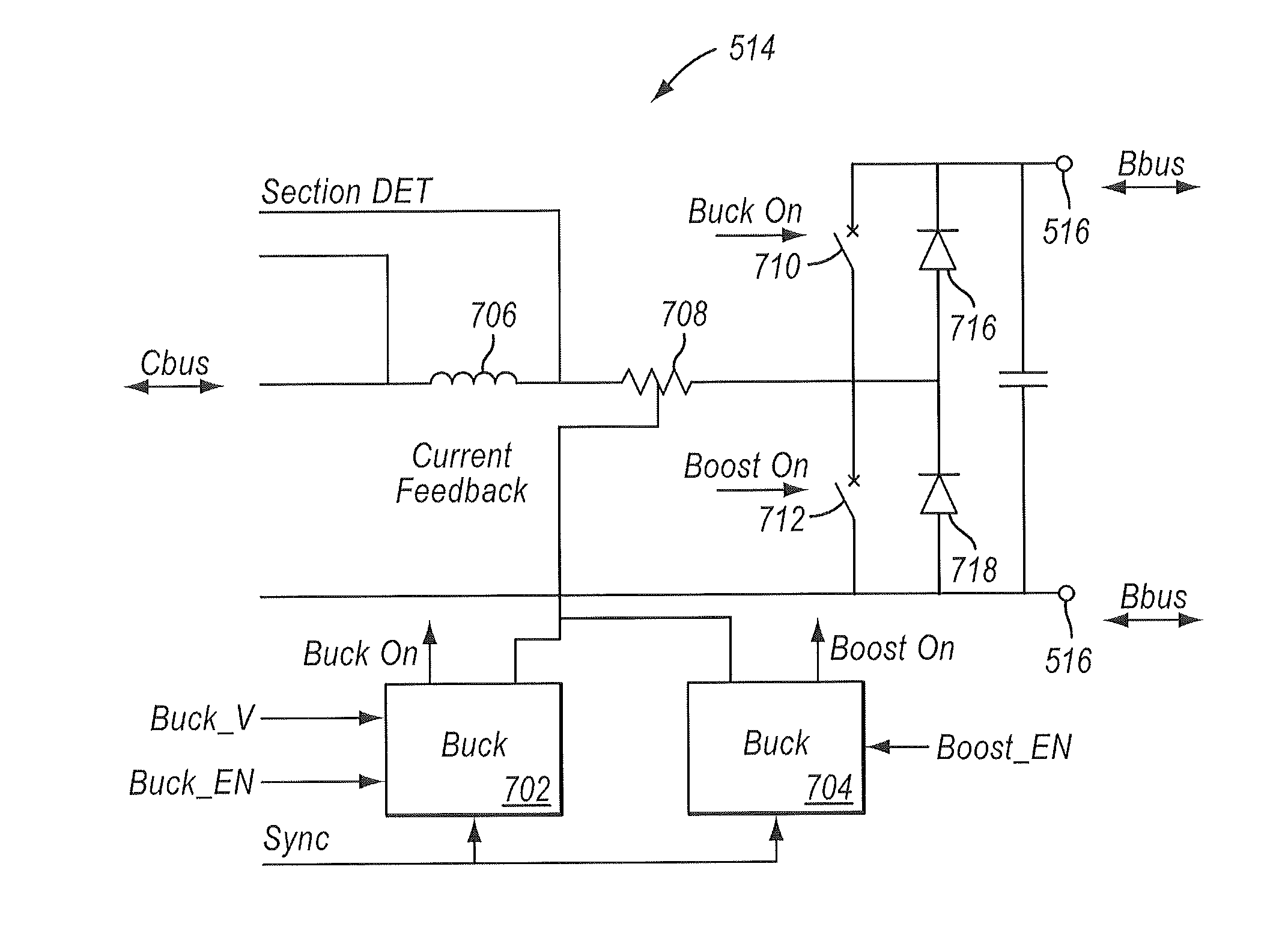
[0026]One embodiment of the buck-boost circuit is described below in the context of a flow cell battery system. However, buck-boost circuits similar to those described herein may be used in numerous other applications and are not limited to the use described below. Controller circuitry such as the processo...


PUM

PropertyMeasurementUnit
voltageaaaaaaaaaa
voltageaaaaaaaaaa
voltageaaaaaaaaaa

Abstract

In accordance with some embodiments, a buck-boost circuit is contemplated which is bi-directional. That is, the buck-boost circuit be configured to produce a load voltage for a load responsive to a source voltage from a voltage source, and the buck-boost circuit may also be configured to produce a charging voltage for the voltage source responsive to a second voltage source connected to the load. In an embodiment, the buck-boost circuit may be operating in boost mode when providing the load voltage and may be operating in buck mode when providing the charging voltage.

Description

PRIORITY CLAIM[0001]This application claims the benefit of U.S. Provisional Application No. 61 / 182,082 entitled “BUCK-BOOST CONTROL CIRCUIT” filed on May 28, 2009.BACKGROUND OF THE INVENTION[0002]1. Field of the Invention[0003]Embodiments disclosed herein may be directed to a circuit for controlling a buck-boost operation performed by one or more buck-boost converters.[0004]2. Description of the Related Art[0005]A buck-boost converter is a DC-DC converter that typically produces an output voltage which is either greater than or less than the input voltage. The buck-boost converter may further be seen as a switch mode power supply having a similar circuit topology from individual buck and boost converters. FIG. 1 is a diagram illustrating a conventional buck-boost converter 100. As shown in FIG. 1, buck-boost converter 100 includes a power source 102 coupled in parallel to an inductor 104, a capacitor 106, and a load 108, shown in FIG. 1 as a resistor. Buck-boost converter also inclu...

Claims


Application Information

Patent Timeline
Patent Type & Authority Applications(United States)
IPC IPC(8): H02J7/00G05F1/10H02J1/00
CPCH02M3/1582H02M1/32H02M3/1584H02M1/08H02M1/0009
Inventor PARAKULAM, GOPALAKRISHNAN R.AGRAWAL, BINOD KUMARSAHU, SAROJ KUMAR
Owner IMERGY POWER SYST
Why Eureka
Try Eureka