Integrated fuel catalyst monitor

a catalyst monitor and fuel catalyst technology, applied in the direction of electric control, machines/engines, mechanical equipment, etc., can solve the problems of specific nox trapping catalyst requirements that may be ineffective for lower emission regulations, reduce efficiency, and risk of catalyst oversaturation, so as to reduce the reduction of combustion by-products, reduce the risk of oversaturation, and reduce the effect of emissions

Active Publication Date: 2011-04-14
FORD GLOBAL TECH LLC
View PDF3 Cites 21 Cited by
  • Summary
  • Abstract
  • Description
  • Claims
  • Application Information

AI Technical Summary

Benefits of technology

[0002]A three-way catalyst device coupled to the exhaust of a combustion engine reduces combustion by-products such as carbon monoxide, hydrocarbons, and oxides of nitrogen. However, as the catalyst device ages, its ability to store oxygen diminishes leading to a decrease in efficiency. In order to determine the efficiency of the catalyst device, systems monitor the ability of the device to store oxygen.
[0004]However, the inventors have recognized issues with such an approach. For example, lean combustion may lead to specific NOx trapping catalyst requirements that may be ineffective for lower emission regulations. Further, in such an approach, since combustion is taking place while the catalysts are saturated for monitoring, there may be a risk of catalyst oversaturation. Catalyst oversaturation may result in decreased reduction of combustion by-products.
[0005]As such, the above issued may be addressed at least partially be running a catalyst monitor following deceleration fuel shut-off (DFSO) events, as such operation may provide an advantageous starting point for monitoring the efficiency of the catalysts in an emission control device. In particular, running the monitoring routine following DFSO eliminates the need to operate the engine in a lean combustion mode in order to saturate the catalyst. Further, during DFSO no fuel is injected while the engine rotates and pumps air through the catalyst, thus catalytic saturation may occur faster and more completely than during lean engine operation, with reduced risks from oversaturation.
[0006]The inventors herein have also recognized that including compensation for air mass and catalyst temperature variations in the catalyst monitoring routine may reduce noise sources in the catalyst monitoring routine.
[0008]In such an approach, the oxygen storage capacity may be identified via an integrated fuel metric. Furthermore, since little to no combustion occurs during DFSO when the catalysts are being saturated, the negative effects of catalyst oversaturation may be reduced.

Problems solved by technology

However, as the catalyst device ages, its ability to store oxygen diminishes leading to a decrease in efficiency.
However, the inventors have recognized issues with such an approach.
For example, lean combustion may lead to specific NOx trapping catalyst requirements that may be ineffective for lower emission regulations.
Further, in such an approach, since combustion is taking place while the catalysts are saturated for monitoring, there may be a risk of catalyst oversaturation.
Catalyst oversaturation may result in decreased reduction of combustion by-products.

Method used


Image

  • Integrated fuel catalyst monitor
  • Integrated fuel catalyst monitor
  • Integrated fuel catalyst monitor

Examples


Embodiment Construction

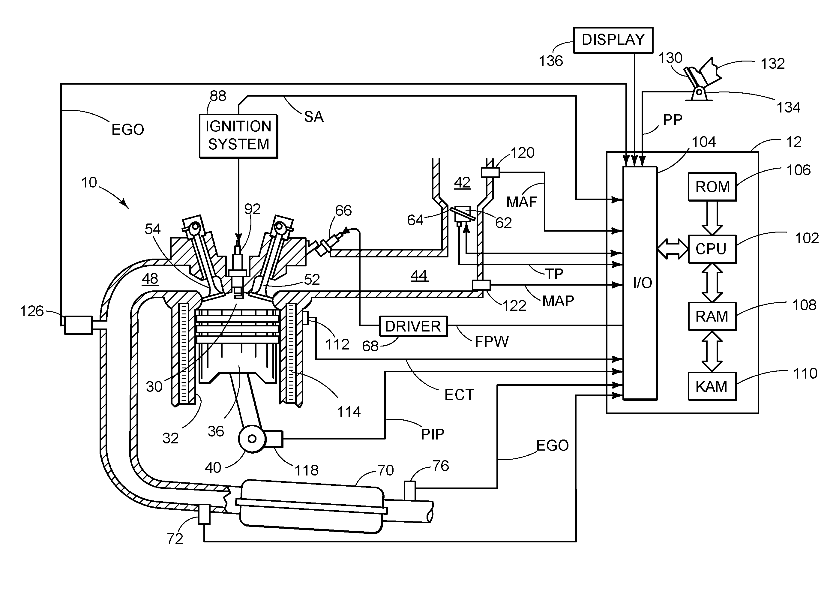
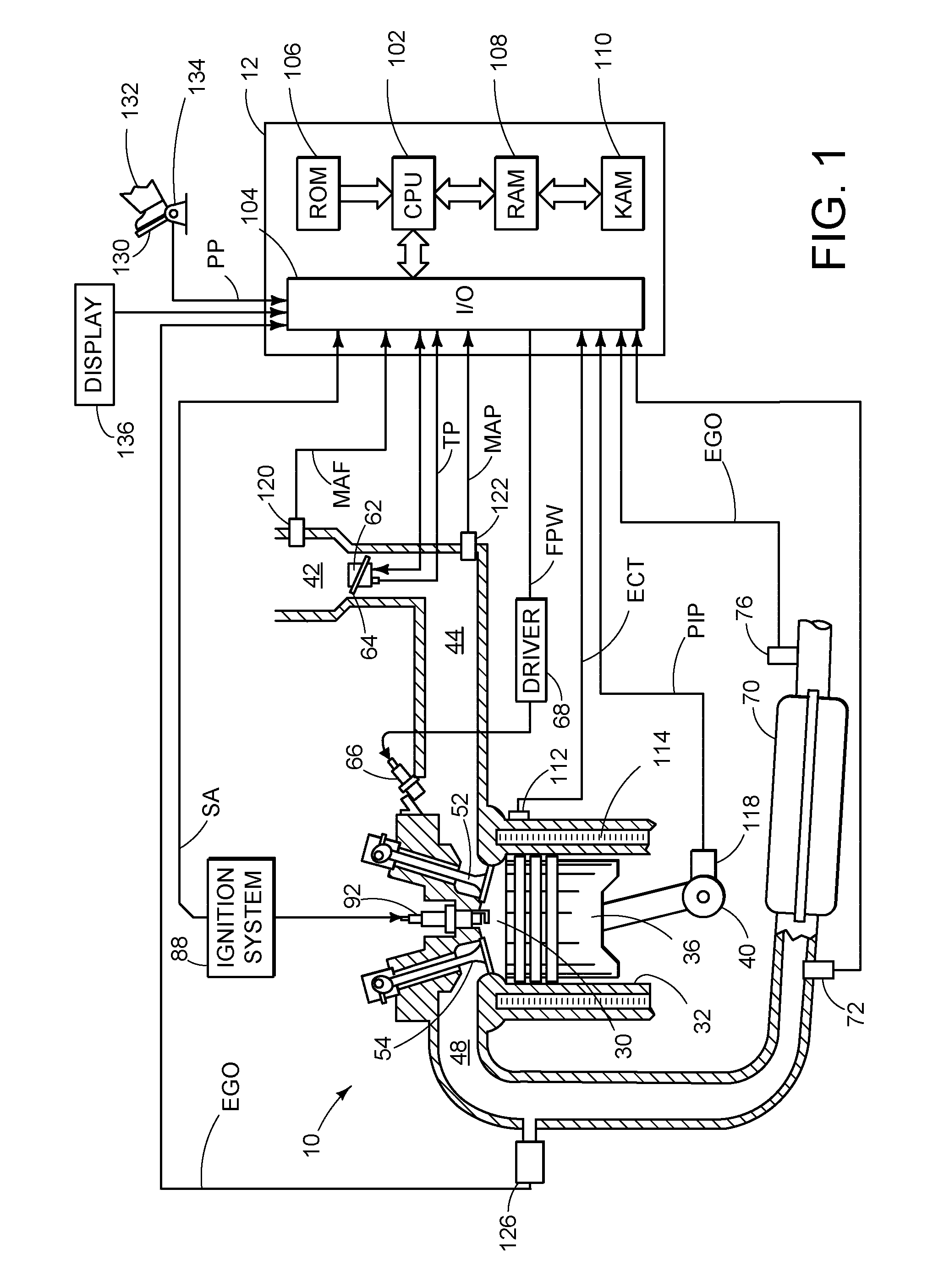
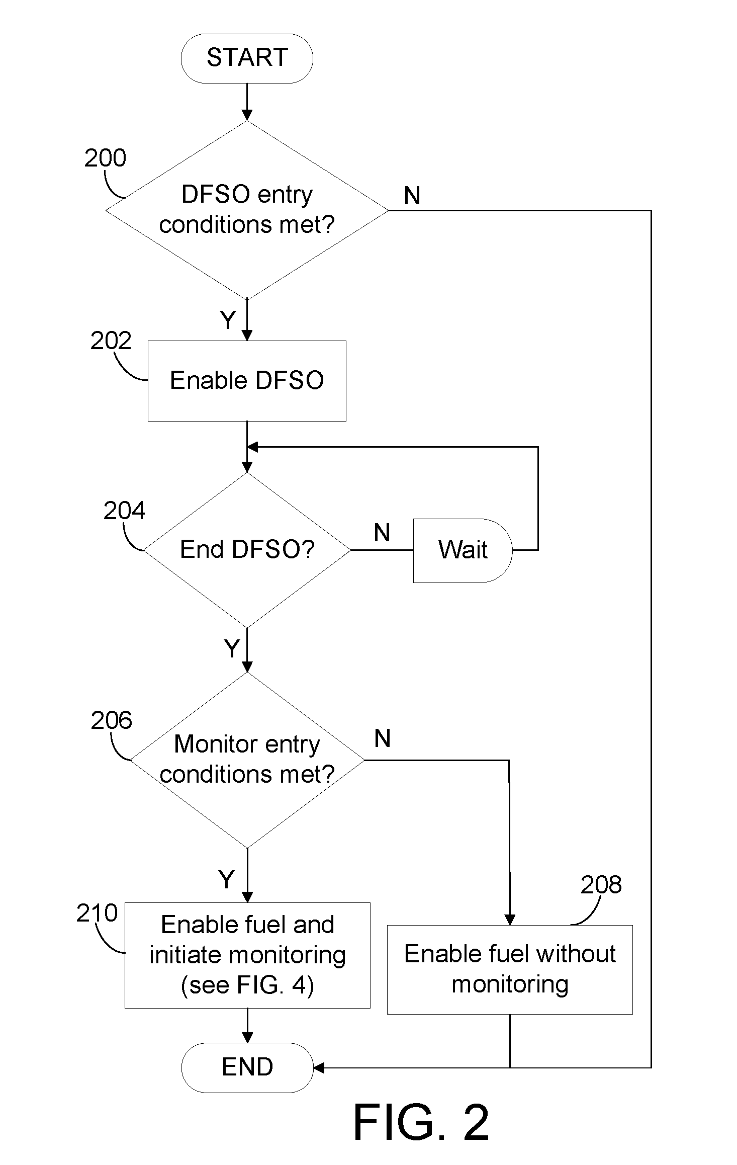
[0017]The following description relates to a system and method for monitoring an emission control system following a deceleration fuel shut-off event. FIG. 1 shows an example combustion engine with an emission control device coupled to the exhaust. The catalyst monitoring routine may be initiated following a DFSO event, in response to a driver tip-in to come out of the DFSO event. FIGS. 3A, 3B, and 3C show examples of air-fuel variations of a fuel injector, an air-fuel sensor upstream of the emission control device, and an air-fuel sensor downstream of the emission control device, respectively, during an example catalyst monitoring event. The example catalyst monitoring routine shown in FIG. 4 determines an oxygen storage capacity (OSC) of the catalysts in the emission control device based on an amount of rich products required to cause a sensor to become richer than a threshold. In one example, the sensor may be located at full volume. In another example the sensor may be located a...


PUM


Abstract

A method is provided for monitoring an emission device coupled to an engine. In one example approach, the method comprises: following a deceleration fuel shut-off duration, indicating degradation of the emission device based on an amount of rich products required to cause a sensor to become richer than a threshold. The amount of rich products required may be correlated to an amount of oxygen stored in the emission device. The indication of emission device degradation may be further based on air mass and temperature during delivery of the required rich products.

Description

FIELD[0001]The present disclosure relates to a catalyst monitoring system.BACKGROUND AND SUMMARY[0002]A three-way catalyst device coupled to the exhaust of a combustion engine reduces combustion by-products such as carbon monoxide, hydrocarbons, and oxides of nitrogen. However, as the catalyst device ages, its ability to store oxygen diminishes leading to a decrease in efficiency. In order to determine the efficiency of the catalyst device, systems monitor the ability of the device to store oxygen.[0003]Various approaches, including full and partial volume monitoring sensor approaches have been developed. In one approach, as described in U.S. Pat. No. 6,594,986, monitoring of the emission control device with a lean-burn engine includes monitoring the oxygen storage capacity of the device by determining an amount of fuel required to purge the catalysts after they have been fully saturated with oxidants due to lean operation.[0004]However, the inventors have recognized issues with suc...

Claims


Application Information

Patent Timeline
Patent Type & Authority Applications(United States)
IPC IPC(8): F01N11/00F02D43/00
CPCF01N3/101F01N11/007F01N2550/02F01N2560/025F02D41/0235Y02T10/22F02D41/1441F02D41/1454F02D2200/0802F02D2200/0814Y02T10/47F02D41/123Y02T10/12Y02T10/40
Inventor SEALY, BRENT EDWARDHEPBURN, JEFFREY SCOTTDARA, PAUL CHESTER
Owner FORD GLOBAL TECH LLC
Why Eureka
Try Eureka