Waste Heat Recovery System and Method Thereof

Inactive Publication Date: 2011-04-14
YOON YONG K
View PDF10 Cites 19 Cited by
  • Summary
  • Abstract
  • Description
  • Claims
  • Application Information

AI Technical Summary

Benefits of technology

[0034]The advantages of the present invention are: (1) the waste heat recovery system captures steam from a heat exchanger and liquefies t

Problems solved by technology

In a thermal application such as a boiler, waste heat problem has been there all the time.
Due to the first law of thermodynamics, it seems to be unavoidable that a part of heat input to a thermal application is output into outsi

Method used


Image

  • Waste Heat Recovery System and Method Thereof
  • Waste Heat Recovery System and Method Thereof
  • Waste Heat Recovery System and Method Thereof

Examples


Example

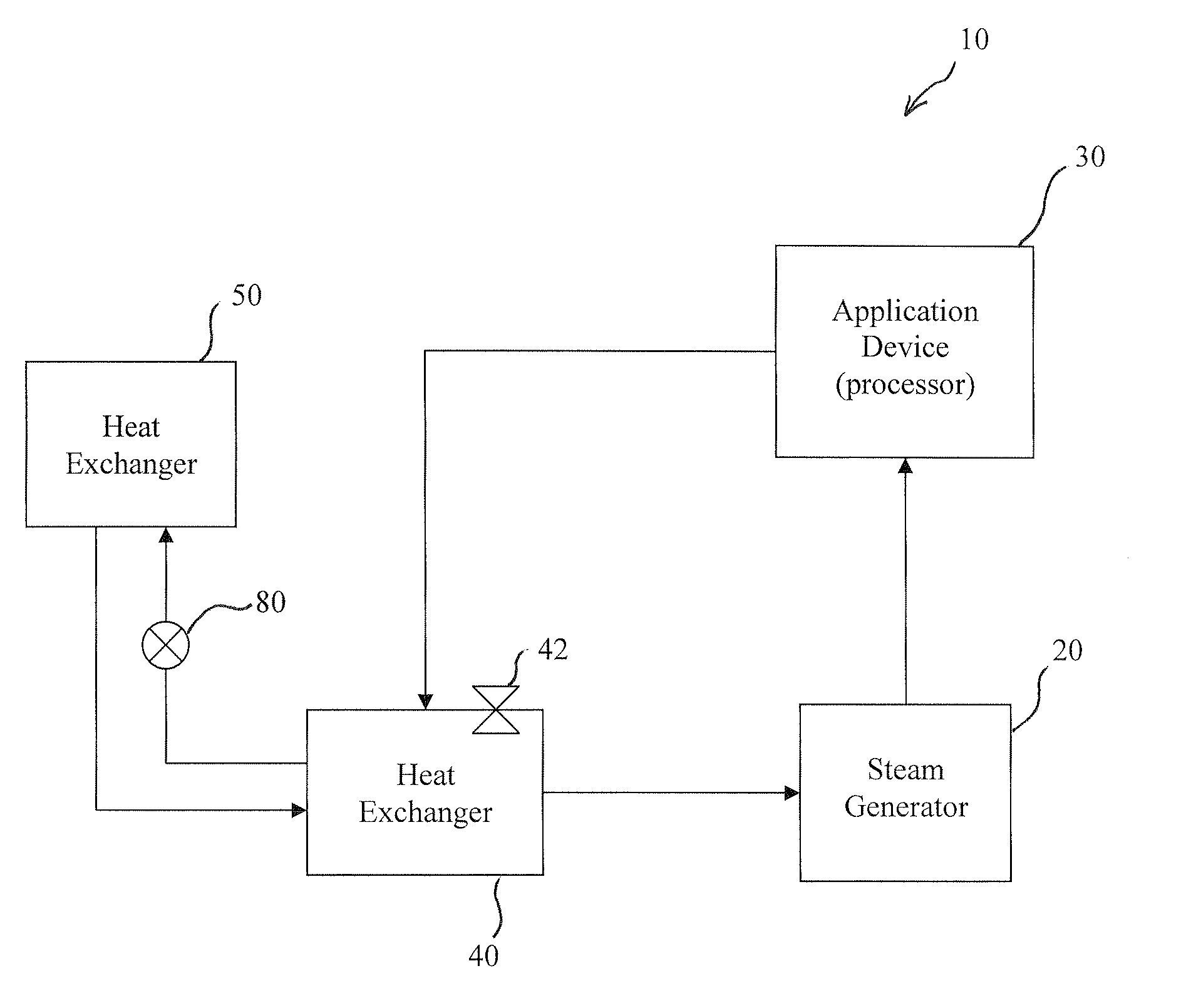
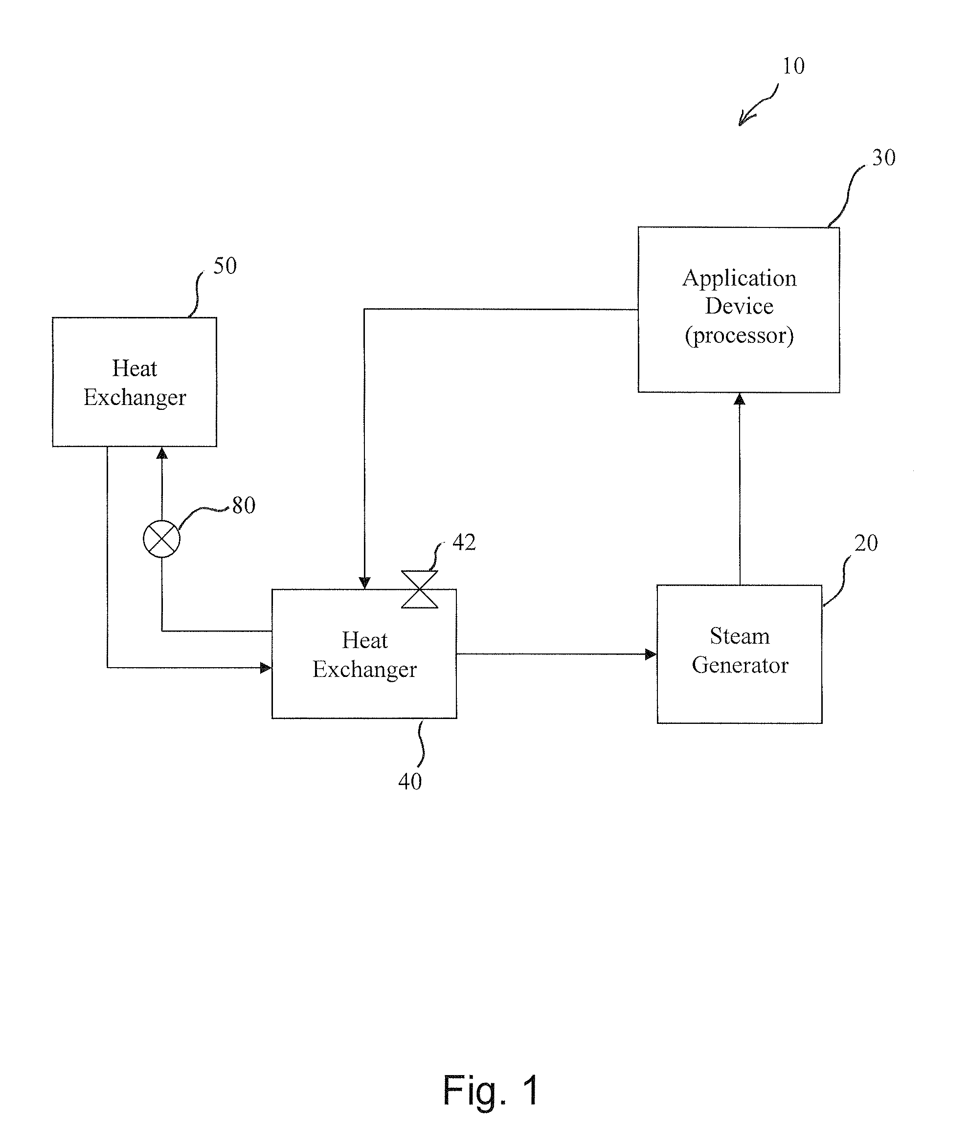
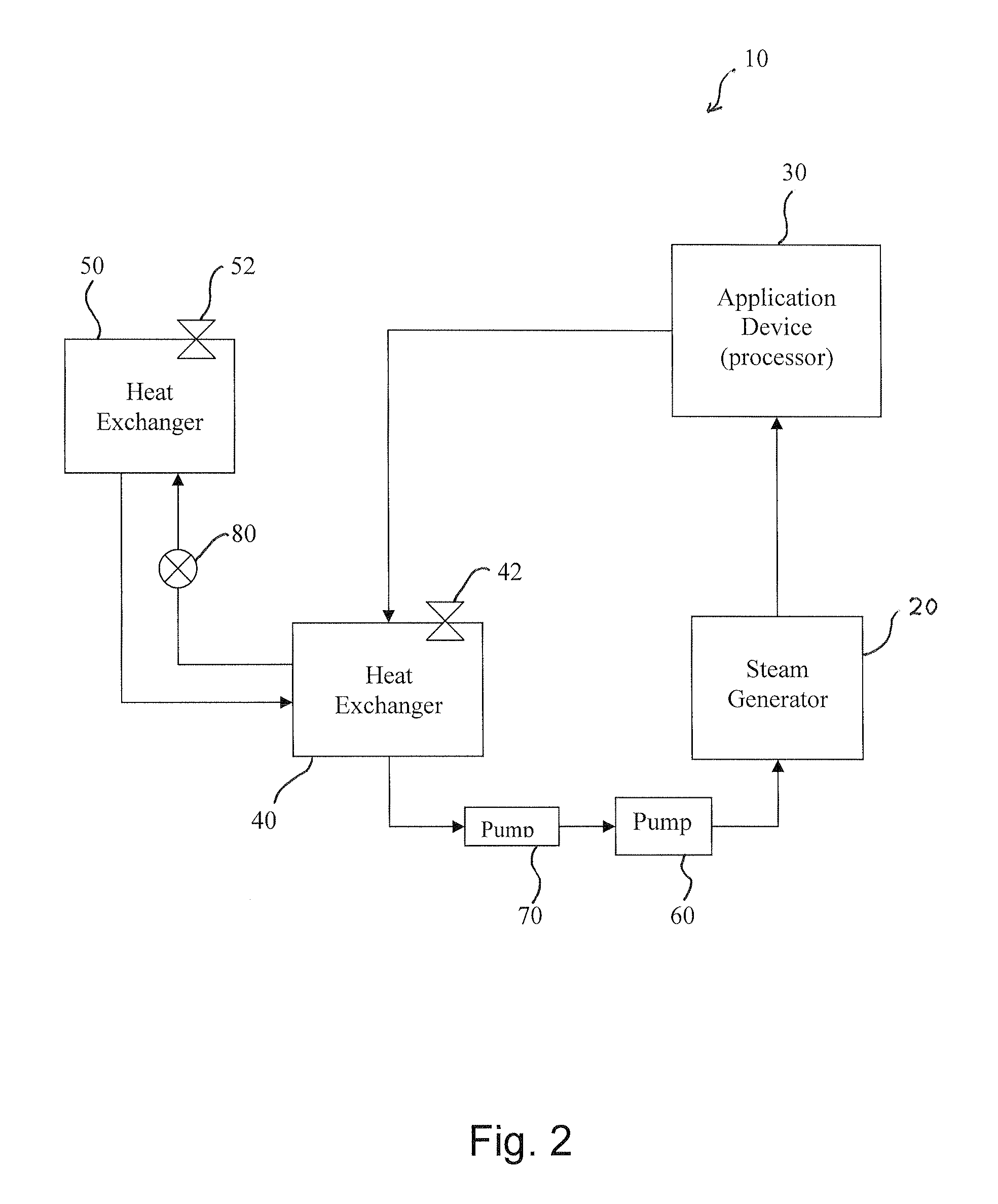
[0046]FIG. 1 is a schematic block diagram of a waste heat recovery system 10 according to an embodiment of the present invention. FIG. 2 is a schematic block diagram of a waste heat recovery system 10 according to another embodiment of the present invention. FIG. 3 is a schematic block diagram of a waste heat recovery system 10 according to still another embodiment of the present invention.

[0047]The waste heat recovery system 10 comprises a steam generator 20, a processor 30, a first heat exchanger 40, and a second heat exchanger 40.

[0048]The steam generator 20 is configured for generating an original steam using water.

[0049]The processor 30 is configured to use the original steam from the steam generator 20 and emit water and a first steam. The processor 30 may include a plurality kinds of thermal applications such as boiler systems and steam engines, which take in steam of high temperature and pressure to exert work to internal or external loads. The first steam usually has temper...


PUM


Abstract

A waste heat recovery system comprises a steam generator, a processor, a first heat exchanger, and a second heat exchanger. The steam generator generates an original steam using water. The first heat exchanger condensates the first steam and emit water and a second steam from the processor. The second heat exchanger condensates the second steam from the first heat exchanger. The second heat exchanger condensates the second steam from the first heat exchanger leaving water only. The water from the first heat exchanger and the second heat exchanger may be guided into the steam generator or into the first heat exchanger. The second heat exchanger comprises one or more pressure relief valve. The pressure relief valve operates when inner pressure of the second heat exchanger exceeds above a predetermined value.

Description

BACKGROUND OF THE INVENTION[0001]The present invention relates to a waste heat recovery system and method thereof. More particularly, this invention relates to a waste heat recovery system and method, which enables to minimize the amount of waste heat discarded from a thermal application.[0002]In a thermal application such as a boiler, waste heat problem has been there all the time. Due to the first law of thermodynamics, it seems to be unavoidable that a part of heat input to a thermal application is output into outside of the thermal application. That is, since it is impossible to create a thermal application having 100% of efficiency, the residue heat, the heat input minus the word done by the thermal application, is always larger than zero.[0003]The waste heat has been dumped out of the thermal application as a form of still hot water or steam.[0004]Even though the train is not powered by a steam engine any more, a plurality of thermal applications are present in our technologic...

Claims


Application Information

Patent Timeline
IPC IPC(8): F22B1/18
CPCF01K9/00
Inventor YOON, YONG K.
Owner YOON YONG K
Why Eureka
Try Eureka