
Sewage waste heat recovery device and working method thereof

A waste heat recovery device and working method technology, applied in chemical instruments and methods, water/sludge/sewage treatment, water aeration, etc., can solve the problem of clean sewage flow, uncontrollable temperature, heat discharge pollution of natural environment, water data Waste of energy and other issues, to achieve the effect of controlling the flow of sewage and clean water, facilitating maintenance and effective recycling

Pending Publication Date: 2021-04-16
HUADIAN ELECTRIC POWER SCI INST CO LTD
View PDF1 Cites 0 Cited by
  • Summary
  • Abstract
  • Description
  • Claims
  • Application Information

AI Technical Summary

Problems solved by technology

[0002] In daily production and daily life, various kinds of sewage containing high heat will be produced. For example, coal mine enterprises will produce a large amount of bathing wastewater, thermal power plants will produce more boiler sewage and other drainage, etc., which are often directly discharged, not only It causes the waste of water materials and energy loss, and also causes certain heat emission pollution to the natural environment.
[0003] At this stage, there is a patent application for heat recovery from sewage. The publication date is February 28, 2020. In the Chinese patent with the publication number CN210118815U, a utility model named "a sewage heat recovery heating device" is disclosed. New type patent; this patent application recovers the heat of the sewage through the heat pump and uses it for heating, but there are still problems such as the flow and temperature of the clean sewage during the heat exchange process cannot be controlled, so it still has the above defects

Method used


Image

  • Sewage waste heat recovery device and working method thereof

Examples


Embodiment Construction

[0016] The present invention will be further described in detail below in conjunction with the accompanying drawings and examples. The following examples are explanations of the present invention and the present invention is not limited to the following examples.

[0017] Example.

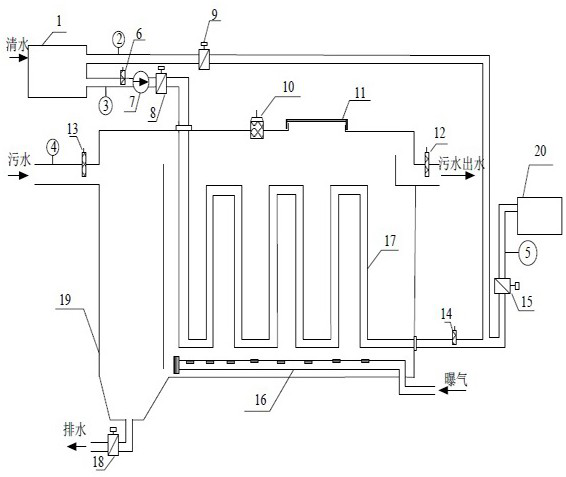
[0018] see figure 1 , The sewage waste heat recovery device in this embodiment includes a clean water buffer tank 1, a first flow meter 2, a second flow meter 3, a third flow meter 4, a fourth flow meter 5, a first water temperature sensor 6, a water supply pump 7, a first Valve 8, second valve 9, liquid level gauge 10, inspection port 11, second water temperature sensor 12, third water temperature sensor 13, fourth water temperature sensor 14, third valve 15, aeration device 16, heat exchanger 17, The fourth valve 18, the heat exchange device 19 and the clean water recycling tank 20.

[0019] In this embodiment, the clear water buffer tank 1 is connected to the inlet of the water supply pump 7, ...


PUM


Abstract

The invention relates to a sewage waste heat recovery device and a working method thereof, and belongs to the field of sewage treatment and energy conservation. The sewage waste heat recovery device comprises a clear water buffer tank, a water supply pump, a first valve, a second valve, a third valve, an aeration device, a heat exchanger, a fourth valve, a heat exchange device and a clear water recycling tank, wherein the clear water buffer tank is connected with the water supply pump; an outlet of the water supply pump is connected with an inlet of the heat exchanger; the first valve is arranged between the outlet of the water supply pump and the inlet of the heat exchanger; the heat exchanger is installed in the heat exchange device, the outlet of the heat exchanger is connected with the clear water buffer tank and the clear water recycling tank; the second valve is installed on a branch pipe connected to the clear water buffer tank; the third valve is installed on another branch pipe connected to the clear water recycling tank; the aeration device is arranged at the bottom of the heat exchange device; and the fourth valve is arranged on a drain outlet pipeline at the bottom of the heat exchange device. The sewage waste heat recovery device is simple and reasonable in structural design, can effectively recover waste heat of sewage, prevents impurities from adhering to the interior of the heat exchange device and the surface of the heat exchanger, and meets usage requirements.

Description

technical field [0001] The invention relates to a device and a method, in particular to a sewage waste heat recovery device and a working method thereof, which belong to the field of sewage treatment and energy saving. Background technique [0002] In daily production and daily life, various kinds of sewage containing high heat will be produced. For example, coal mine enterprises will produce a large amount of bathing wastewater, thermal power plants will produce more boiler sewage and other drainage, etc., which are often directly discharged, not only It causes the waste of water materials and the loss of energy, and also causes certain heat emission pollution to the natural environment. [0003] At this stage, there is a patent application for heat recovery from sewage. The publication date is February 28, 2020. In the Chinese patent with the publication number CN210118815U, a utility model named "a sewage heat recovery heating device" is disclosed. New type patent; this ...

Claims


Application Information

Patent Timeline
IPC IPC(8): F28D21/00F28F27/02C02F7/00
CPCY02W10/10
Inventor 张山山吴巧玲姬海宏李廷豪
Owner HUADIAN ELECTRIC POWER SCI INST CO LTD
Learn More