Check patentability & draft patents in minutes with Patsnap Eureka AI!

Portable gas powered internal combustion engine arrangement

Inactive Publication Date: 2011-04-14
LEHR IP LLC
View PDF63 Cites 6 Cited by
  • Summary
  • Abstract
  • Description
  • Claims
  • Application Information

AI Technical Summary

Benefits of technology

[0024]The above described mounting of the Coleman Bottles on the mounting plate to be in thermal transfer relationship thereto for receiving heat as generated in the cylinder of the internal combustion engine as well as receiving vibration therefrom uniquely allows the continuous flow of larger amounts of gas from the LPG to thereby allow the powering of larger internal combustion engines and demand devices. The heat transferred to the Coleman Bottles heats the LPG contained therein to increase the evaporation of gas therefrom. The heat thus transferred to the LPG tends to keep the temperature of the liquid LPG above the freezing point even though comparatively larger amounts of gas are evaporated therefrom. The direct transfer of heat from the engine to the Coleman bottle and thus to the LPG therein has a dual benefit: the heat keeps the LPG from freezing and aids in cooling the internal combustion engine during the operation thereof. The transmittal of vibration of the Coleman Bottle by the operation of the engine also agitates the LPG to thus increase the effective surface area thereof thereby allowing even greater flow of gas therefrom and the agitation also helps in preventing the LPG from freezing.
[0030]In some applications of the present invention it has been found that the vibration to which the liquified petroleum gas container is exposed during operation of the internal combustion engine may cause damage to the liquified petroleum gas container to which a rigid hose is utilized for connecting the liquified petroleum gas container to the pressure regulator or to any other component of the system. In an embodiment of the present invention that overcomes the problem of vibration induced damage to the liquified petroleum gas container and / or the hose connection at the output thereof, there is provided in this embodiment a flexible hose for conducting the liquified petroleum gas from the liquified petroleum gas container to the a component of the system. In one variation of this embodiment of the present invention, there is provided an outlet conduit which is a flexible hose having a first end thereof connected to a connector on the outlet of the liquified petroleum gas container to minimize the damaging effect of vibration and the second end of the outlet conduit flexible hose may be connected to, for example, a pressure regulator which is mounted on the internal combustion engine, for example on the carburetor thereof.

Problems solved by technology

However, the storage of gasoline is highly restricted as to the type of container in which it may be stored, the places where it may be stored, the amount that may be stored and the environmental conditions under which it may be stored.
Such devices are, of course, large and cumbersome and not adapted to be a readily portable device that may be easily carried by one person and transported from location to location.
However, there is a demand for an electric power generator that is small and light enough to be moved by one person from location to location and still provide a moderate amount of electrical power.
Such a configuration limits the utility of such a device.
However, the gas flow rate of the gas from the LPG in a Coleman Bottle is limited because of the comparatively small surface area of the LPG from which the gas is generated.
Consequently, despite the attractiveness of the Coleman Bottles for use in many devices, the use of the Coleman Bottles has generally been limited to very low power requirement applications and have not been adapted for use in providing the energy for powering an internal combustion engine utilized to drive an electrical generator or other portable engine driven devices.

Method used


Image

  • Portable gas powered internal combustion engine arrangement
  • Portable gas powered internal combustion engine arrangement
  • Portable gas powered internal combustion engine arrangement

Examples


embodiment 10

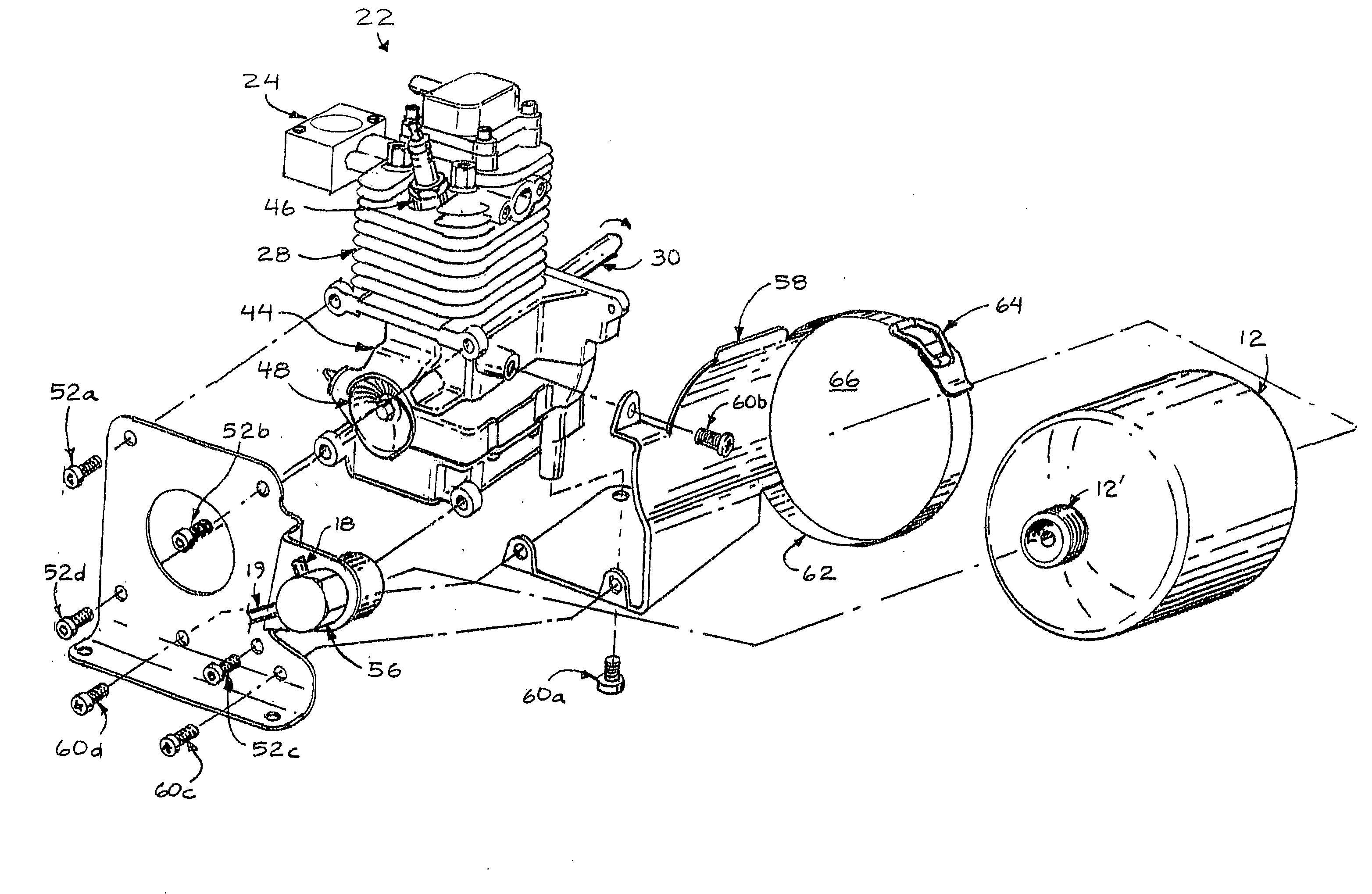
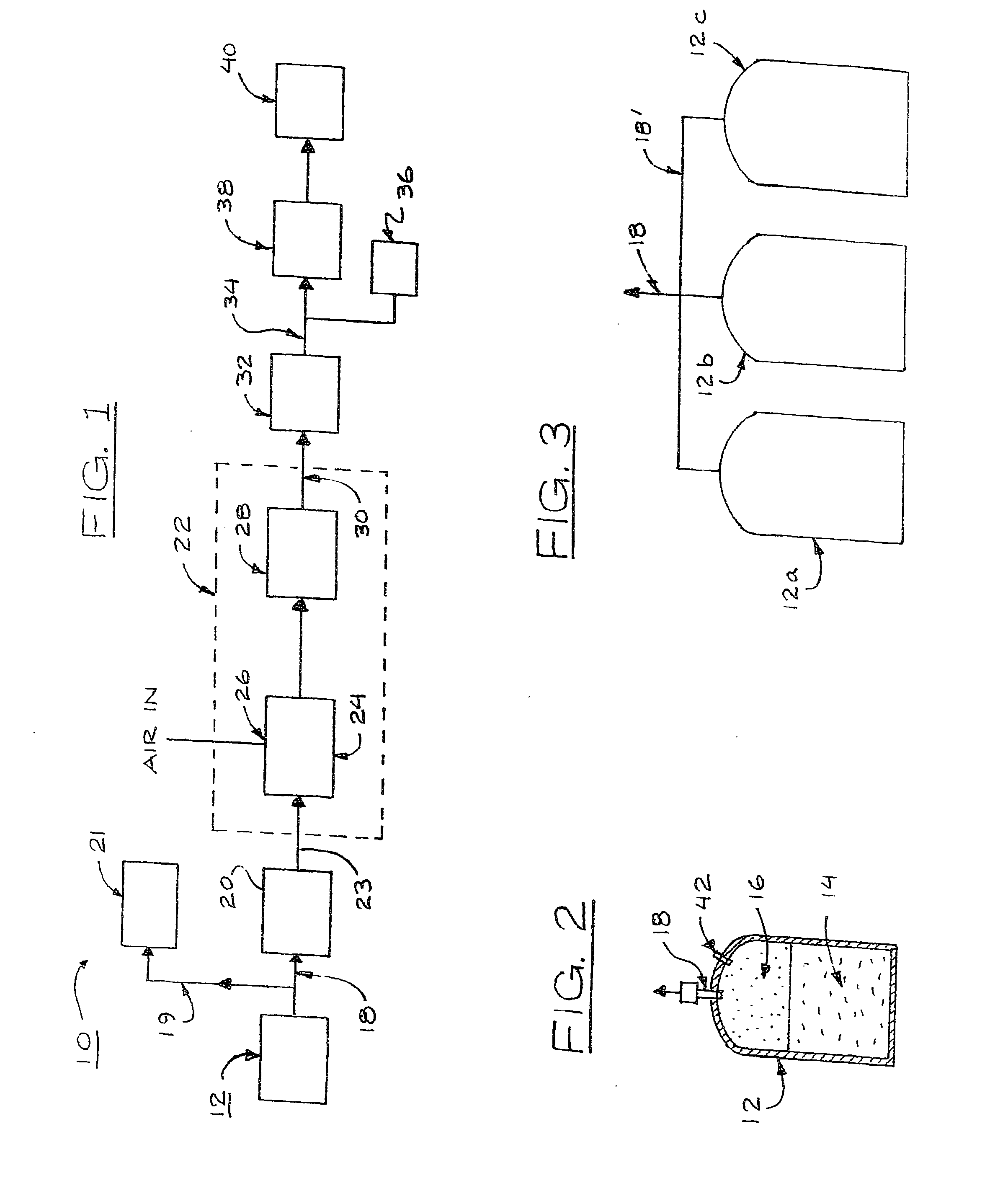
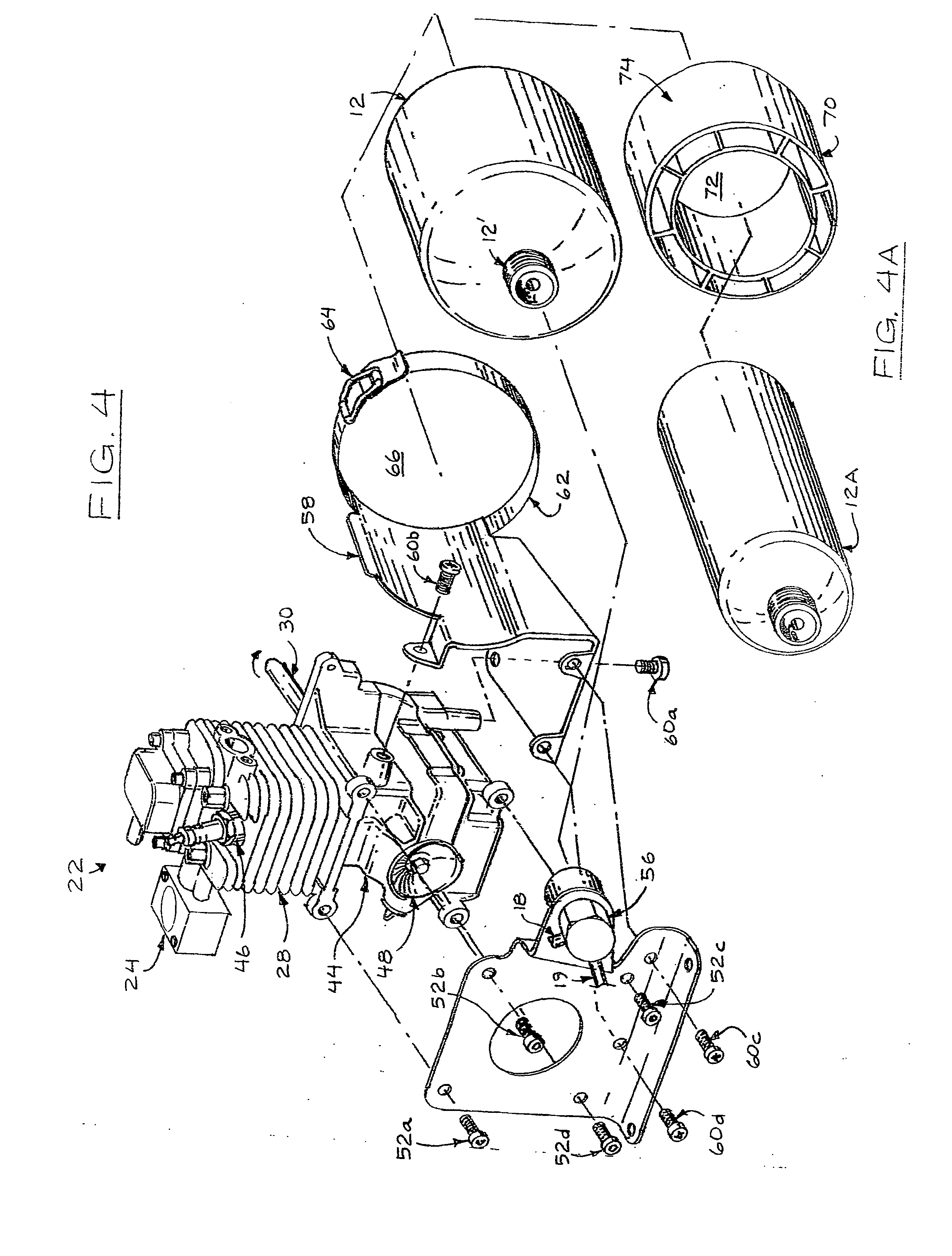
[0057]The gas 16 flowing from the pressure regulator 20 is directed through a delivery conduit 23 into a carburetor 24 that is part of the internal combustion engine 22. The carburetor 24 has an air intake as indicated at 26. The carburetor 24 mixes the gas 16 with the air and provides the mixture to the cylinder 28 of the internal combustion engine 22 in a manner well known. The internal combustion engine 22 has a rotating output shaft 30. In the embodiment 10 the rotating output shaft drives an electric generator 32. The electric generator 32 provides electric energy as indicated at 34 and may be, for example in the power range of 300 to 1000 watts though larger power generators may be utilized in other applications. The electric energy may, if desired, be directed to provide 12 volt DC current as indicted at 36 or may be passed into an invertor 38 for conversion to 120 volts AC, 60 cycle as indicted at 40.

[0058]As noted above, the internal combustion engine 22 may be a four strok...

embodiment 100

[0067]FIG. 10 illustrates an embodiment 100 of the present invention as utilized to power an trimmer 102. As shown on FIG. 10, there is provided an internal combustion engine 22 powered by gas from an LPG container 12 and the internal combustion engine 22 rotates an output shaft 30′ to rotate the trimmer. Thus, the internal combustion engine and LPG container replace the gasoline powered engine and gasoline tank often utilized in such applications.

[0068]FIG. 11 illustrates an embodiment 110 of the present invention in which an internal combustion engine 22 powered by the gas from an LPG container 12 drives a fan 112 to provide a leaf blower 114. In embodiment 110 the internal combustion engine 22 and LPG bottle 12 replace the gasoline powered internal combustion engine and gasoline storage tank often utilized in such applications.

[0069]In some applications of the principles of the present invention, it has been found that excessive vibration generated by some engines and / or usage of...

embodiment 140

[0073]In a variation of the embodiment 140, the pressure regulator 120 may be line mounted between the LPG bottle and the internal combustion engine 122. In such an arrangement either the outlet conduit 118 or the delivery conduit 123, or both, may be flexible hose and the other conduit may be a rigid tube as may be selected for particular applications. The flexible delivery conduit 123 and / or the flexible outlet conduit prevents damage due to relative movement between the LPG bottle 112 and the internal combustion engine 122.


PUM


Abstract

A gas powered internal combustion engine in which the gas is provided from the gas phase of a pressurized liquid gas in an liquified petroleum gas container and in which the liquified petroleum gas container is rigidly mounted adjacent to the internal combustion engine at a preselected angle to be in conductive heat transfer relationship to the internal combustion engine and in vibration receiving relationship to the internal combustion engine whereby the liquified gas in the liquified petroleum gas container is heated and vibrated and the effective surface area thereof is thereby increased. A pressure regulator is provided for receiving the gas from the liquid petroleum gas bottle regulating the pressure of the gas transmitted to the internal combustion engine and at least one flexible hose is connected to the pressure regulator for transmitting the gas therethrough.

Description

REFERENCE TO RELATED APPLICATIONS[0001]This application is a continuation in part of co-pending Ser. No. 12 / 655,121, filed Dec. 24, 2009, which is a continuation in part of 12 / 455,407 filed Jun. 3, 2009 now U.S. Pat. No. 7,703,430, which is a continuation of Ser. No. 12 / 221,869, filed Aug. 6, 2008 now U.S. Pat. No. 7,730,868, which is a continuation of Ser. No. 11 / 702,381 filed Feb. 6, 2008 now U.S. Pat. No. 7,424,886, and is a continuation in part of co-pending 12 / 655,144 filed Dec. 24, 2009 which is a continuation of Ser. No. 12 / 455,790 filed Jun. 8, 2009, now U.S. Pat. No. 7,739,996, which is a continuation of Ser. No. 12 / 221,869, filed Aug. 6, 2008 now U.S. Pat. No. 7,730,868, which is a continuation of Ser. No. 11 / 702,381 filed Feb. 6, 2008 now U.S. Pat. No. 7,424,886.BACKGROUND OF THE INVENTION[0002]1. Field of the Invention[0003]This invention relates to a gas powered internal combustion engine which may be utilized to drive a variety of devices and may be utilized in one app...

Claims


Application Information

Patent Timeline
IPC IPC(8): F02M21/06
CPCY02T10/32F02M21/06Y02T10/30
Inventor HERZER, BERNARDO J.
Owner LEHR IP LLC
Features
  • R&D
  • Intellectual Property
  • Life Sciences
  • Materials
  • Tech Scout
  • Unparalleled Data Quality
  • Higher Quality Content
  • 60% Fewer Hallucinations
Learn More