Permanent-magent motor

a permanent magnet, motor technology, applied in the direction of dynamo-electric machines, dynamo-electric circuit shapes/forms/construction, electrical apparatus, etc., can solve the problems of slow increase of production costs for the whole assembly of the motor b>1/b>, and achieve the effect of enhancing assembly efficiency, reducing the thickness of the front and rear parts, and effective reduction of production costs of irony materials

Inactive Publication Date: 2011-04-14
J STAR MOTOR INDAL
View PDF8 Cites 13 Cited by
  • Summary
  • Abstract
  • Description
  • Claims
  • Application Information

AI Technical Summary

Benefits of technology

[0008]In light of the above structure, i.e. the thin irony barrel and the magnet holder, the magnet set can not only maintain the same thickness as that of the conventional irony barrel but also reduce the thickness of the front and rear parts of

Problems solved by technology

For example, the uniform thickness of the irony barrel 2 is costly in material, so that it is difficult to effectively redu

Method used


Image

  • Permanent-magent motor
  • Permanent-magent motor
  • Permanent-magent motor

Examples


Embodiment Construction

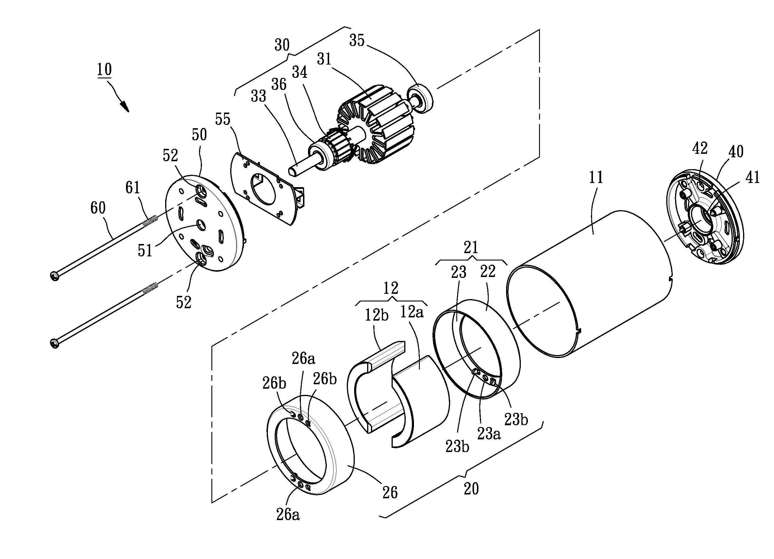
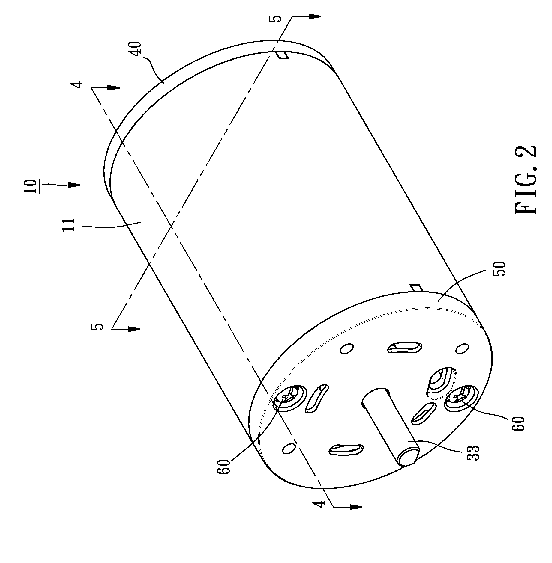
[0018]Referring to FIGS. 2-5, a DC permanent-magnet motor 10 constructed according to a first preferred embodiment of the present invention is composed of a barrel assembly, a rotor assembly 30, a front cover 40, a rear cover 50, and two elongated screw bolts 60.

[0019]The barrel assembly includes an irony barrel 11, a magnet set 12, and a magnet holder 20. The irony barrel 11 includes a thin body. The magnet set 12 is composed of an arched magnets 12a and 12b symmetrically. The magnet holder 20 is composed of a front shell 21 and a rear shell 26. The front shell 21 includes an annular body 22 having an annular end sidewall 23 extending toward an imaginary central axis thereof from a front end edge thereof. The end sidewall 23 includes two through holes 23a running through two opposite sides thereof respectively; and two retaining pieces 23b formed beside each of the two through holes 23a. Each of the retaining pieces 23b is a lug in this embodiment. The rear shell 26 is structurally...


PUM


Abstract

A permanent-magnet motor composed of an irony barrel, a magnet set, a magnet holder, and a rotor. The irony barrel includes a thin body. The magnet set includes a plurality of magnets. The magnet holder is received inside the irony holder and includes a plurality of retaining pieces located at an internal edge thereof for holding the magnet set. The rotor includes a rotor silicon steel sheet, a deflector, a rotary shaft, a front bearing, and a rear bearing, being inserted inside the magnet set. In light of this, the magnet set can not only maintain the same thickness as that of the conventional irony barrel but also reduce the thickness of the front and rear parts of the irony barrel, so that the production cost of the irony material can be effectively decreased. Besides, the magnet holder can definitely space and position the magnets to enhance the assembly efficiency.

Description

BACKGROUND OF THE INVENTION[0001]1. Field of the Invention[0002]The present invention relates generally to motors, and more particularly, to a permanent-motor motor.[0003]2. Description of the Related Art[0004]Referring to FIG. 1, a conventional permanent-magnet motor 1 includes an irony barrel 2 whose body has a uniform thickness W throughout; a magnet set 3 composed of two arched magnets 3a and 3b received in and magnetically attached inside the irony barrel 2; a rotor 4 inserted inside the magnet set 3 and having a rotary shaft 5 inserted through a center thereof; a front cover 6 having an axial hole 6a and two threaded hole 6b, the former of which is provided for a front end of the rotary shaft 5 to pass through; a rear cover 7 structurally similar to the front cover 6 to have an axial hole 7a and two through holes 7b, the former of which is provided for a rear end of the rotary shaft to pass through; and two screw bolts 8 each inserted through one of the two through holes 7b an...

Claims


Application Information

Patent Timeline
IPC IPC(8): H02K1/18
CPCH02K23/04H02K1/17
Inventor HUANG, WEI-MING
Owner J STAR MOTOR INDAL
Why Eureka
Try Eureka