Capacitance sensing circuit with Anti-electromagnetic interference capability

Inactive Publication Date: 2011-04-14
SITRONIX TECH CORP
View PDF9 Cites 18 Cited by
  • Summary
  • Abstract
  • Description
  • Claims
  • Application Information

AI Technical Summary

Benefits of technology

[0007]An objective of the present invention is to provide a capacitance sensing circuit with anti-EMI capability, which uses a difference circuit to eliminate common-mode noise for achieving anti-EMI capability.
[0008]Another objective of the present invention is to provide a capacitance sensing circuit with anti-EMI capability, which adjusts the dynamic range of the output of a filter. Thereby, the capacitance sensing circuit with anti-EMI capability can achieve capacitance sensing in few clock cycles.
[0009]Still another objective if the present invention is to provide a capacitance sensing circuit with anti-EMI capability, which uses a fifth switch and a sixth switch to eliminate influences by parasitic capacitor of the capacitor under test, and hence increasing the dynamic measurement range of the capacitor under test for the capacitance sensing circuit.
[0010]The capacitance sensing circuit with anti-EMI capability according to the present invention comprises a filter and a difference circuit. The filter is coupled to a capacitor under test; receives a plurality of reference signals; and produces a first filter signal and a second filter signal. The difference circuit receives the first and second filter signals; eliminates the common-mode noise in the first and second filter signals; and produces a difference signal. The amplitude of the difference signal is related to the capacitance value of the capacitor under test. Thereby, the purpose of sensing capacitance can be achieved. In addition, by eliminating common-mode noise using the difference circuit, the anti-EMI capability can be achieved. Because the difference circuit can adjust the dynamic range of the output of the filter, the capacitance sensing circuit with anti-EMI capability can achieve capacitance sensing in few clock cycles.

Problems solved by technology

Nevertheless, the technologies shown in FIGS. 1 to 3 lack immunity to EMI.
When electromagnetic noise is coupled to the comparators via capacitors, oscillation frequencies will distort or the initial voltage will vary, and hence resulting in errors in capacitance detection.

Method used


Image

  • Capacitance sensing circuit with Anti-electromagnetic interference capability
  • Capacitance sensing circuit with Anti-electromagnetic interference capability
  • Capacitance sensing circuit with Anti-electromagnetic interference capability

Examples


Embodiment Construction

[0026]In order to make the structure and characteristics as well as the effectiveness of the present invention to be further understood and recognized, the detailed description of the present invention is provided as follows along with embodiments and accompanying figures.

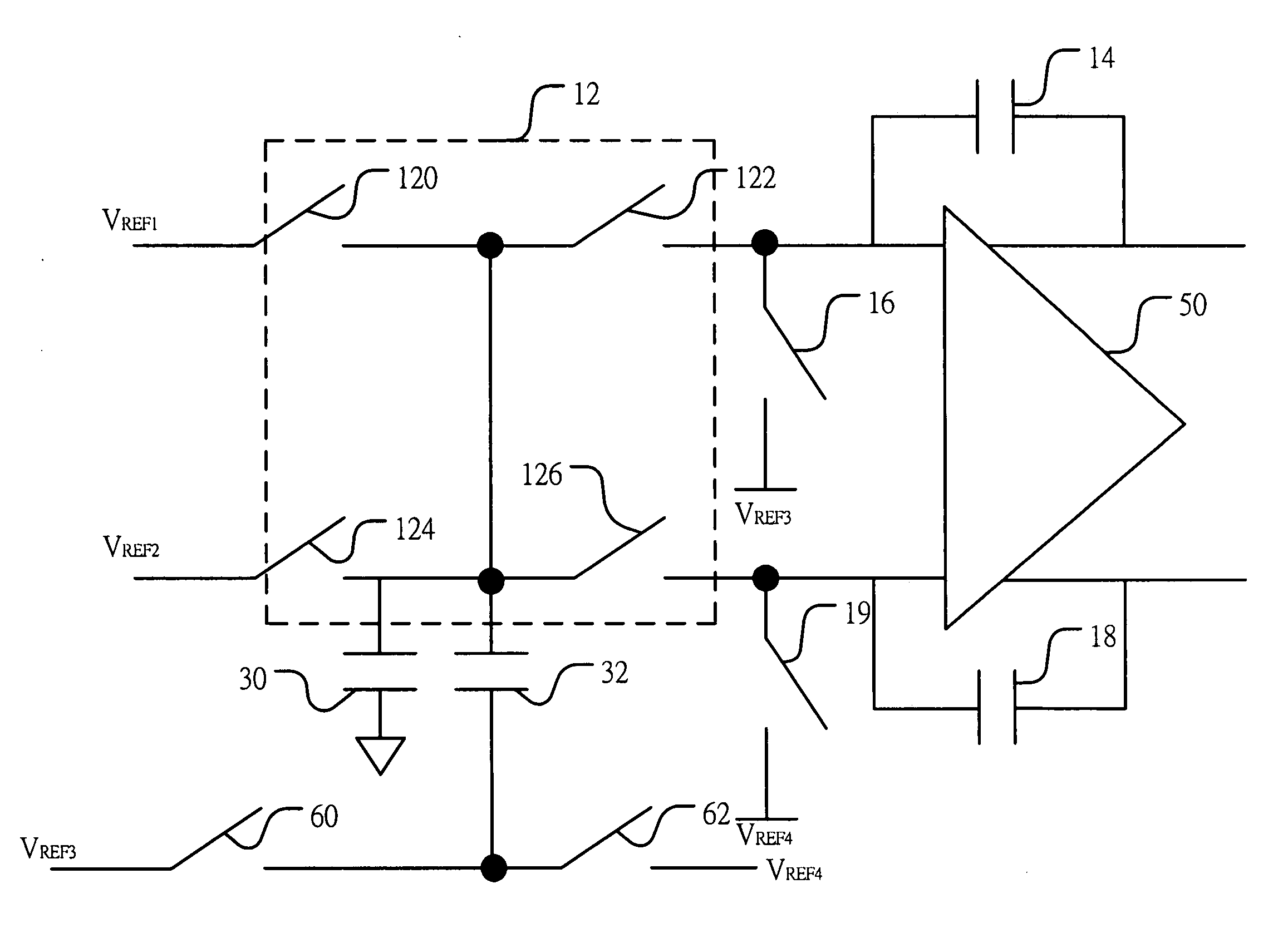
[0027]FIG. 4 shows a block diagram of a capacitance sensing circuit according to a preferred embodiment of the present invention. As shown in the figure, the capacitance sensing circuit with anti-EMI capability can be applied to fingerprint identification, accelerometers, and touch panels. The capacitance sensing circuit comprises a filter 10 and a difference circuit 20. The filter 10 is coupled to a capacitor under test 30; receives a plurality of reference signals; and produces a first filter signal and a second filter signal. Namely, the filter 10 receives a first reference signal VREF1, a second reference signal VREF2, a third reference signal VREF3, and a fourth reference signal VREF4 and produces the first an...


PUM


Abstract

The present invention relates to a capacitance sensing circuit with anti-EMI capability. A filter is coupled to a capacitor under test; receives a plurality of reference signals; and produces a first filter signal and a second filter signal. A difference circuit receives the first and second filter signals; eliminates the common-mode noise in the first and second filter signals; and produces a difference signal. The amplitude of the difference signal is related to the capacitance value of the capacitor under test. Thereby, the purpose of sensing capacitance can be achieved. In addition, by eliminating common-mode noise using the difference circuit, the anti-EMI capability can be achieved. Because the difference circuit can adjust the dynamic range of the output of the filter, the capacitance sensing circuit with anti-EMI capability can achieve capacitance sensing in few clock cycles.

Description

FIELD OF THE INVENTION[0001]The present invention relates generally to a capacitance sensing circuit, and particularly to a capacitance sensing circuit with anti-electromagnetic interference (EMI) capability.BACKGROUND OF THE INVENTION[0002]The applications of capacitance sensing and detection are increasingly wide spreading owing to the development of modern computer technologies, for example, fingerprint identification, microelectromechanical accelerometers, and capacitive touch panels. The capacitance sensing and detection technology according to the prior art generally adopts the capacitance-to-frequency conversion circuit. FIG. 1 shows a block diagram of a capacitance sensing apparatus according to the prior art. As shown in the figure, a first comparator 100′, a second comparator 102′, a control circuit 104′, and a resistor 106′ form an oscillation circuit, which is coupled to a capacitor under test 108′. Different capacitance values will result in different oscillation freque...

Claims


Application Information

Patent Timeline
IPC IPC(8): G01R27/26
CPCG01D5/24H03K2217/960705G01R27/2605
Inventor CHANG, YU-CHENGCHEN, CHUNG-YUAN
Owner SITRONIX TECH CORP
Why Eureka
Try Eureka