Multi-touch touch device with multiple drive frequencies and maximum likelihood estimation

a multi-touch, drive frequency technology, applied in the direction of instruments, transmission systems, computing, etc., to achieve the effect of reducing or eliminating, reducing or eliminating

Inactive Publication Date: 2011-04-14
3M INNOVATIVE PROPERTIES CO
View PDF87 Cites 164 Cited by
  • Summary
  • Abstract
  • Description
  • Claims
  • Application Information

AI Technical Summary

Benefits of technology

[0013]The measurement unit may also evaluate the first response signal over a first sample time, the first sample time corresponding to a first integer number of periods of the first drive frequency and also to a second integer number of periods of the second drive frequency. The use of such a first sample time to evaluate the first response signal, and optionally to also evaluate response signals sensed from other sense electrodes, can be implemented in such a way as to reduce or eliminate the need to rely on bandpass filters to separate signal components at the different drive frequencies. In general, if the drive unit is configured to deliver two or more (e.g., N, where N≧2) unique drive signals to a corresponding number (N) of unique drive electrodes simultaneously or at overlapping

Problems solved by technology

Each of these techniques has its own capabilities, limitations, and other characteristics, and associated advantages and disadvantages from standpoints such as performance, speed, complexity, cost, and so forth.
For example, the designer of a relatively small touch screen system with low resolution an

Method used


Image

  • Multi-touch touch device with multiple drive frequencies and maximum likelihood estimation
  • Multi-touch touch device with multiple drive frequencies and maximum likelihood estimation
  • Multi-touch touch device with multiple drive frequencies and maximum likelihood estimation

Examples


Embodiment Construction

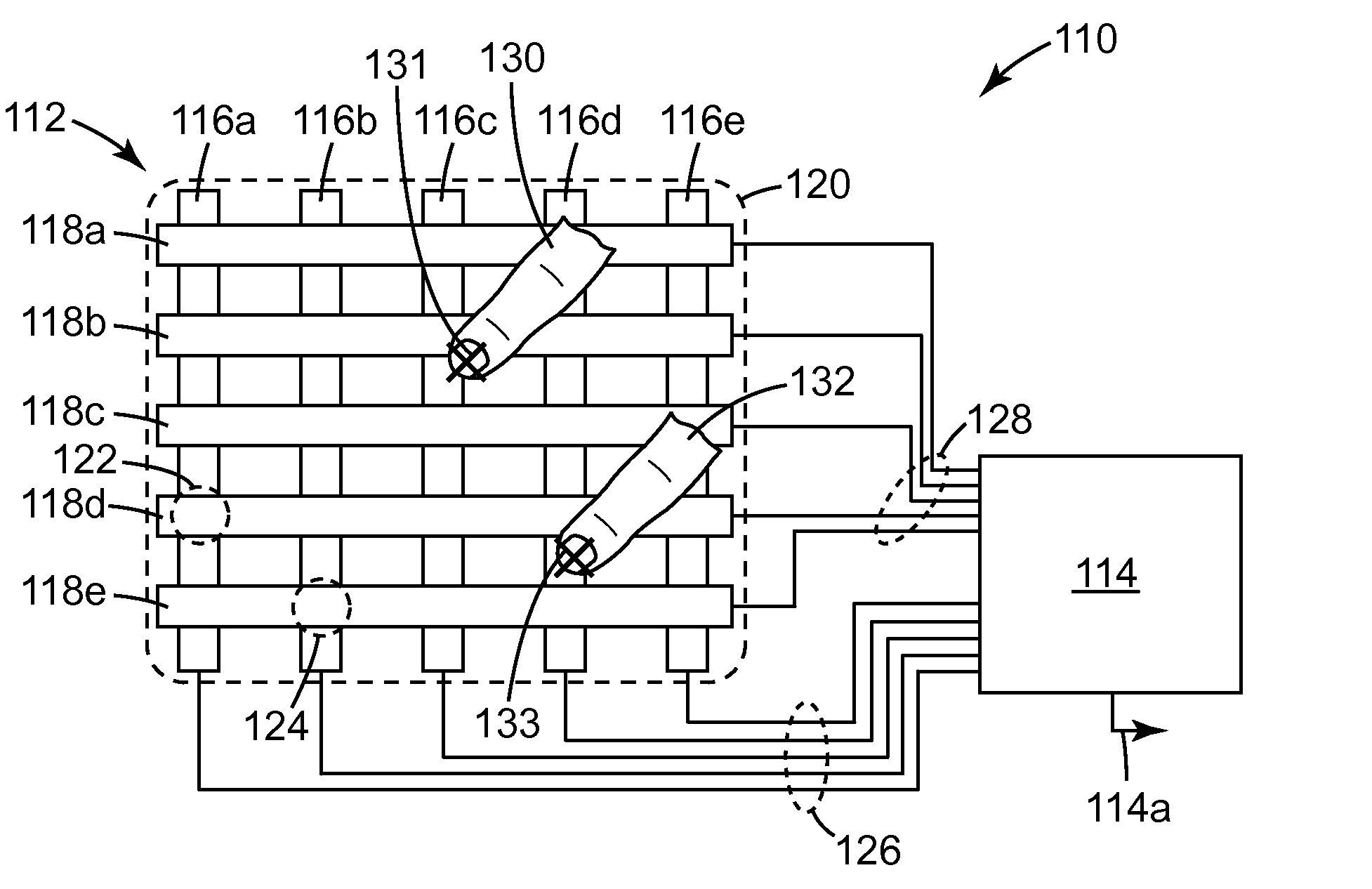
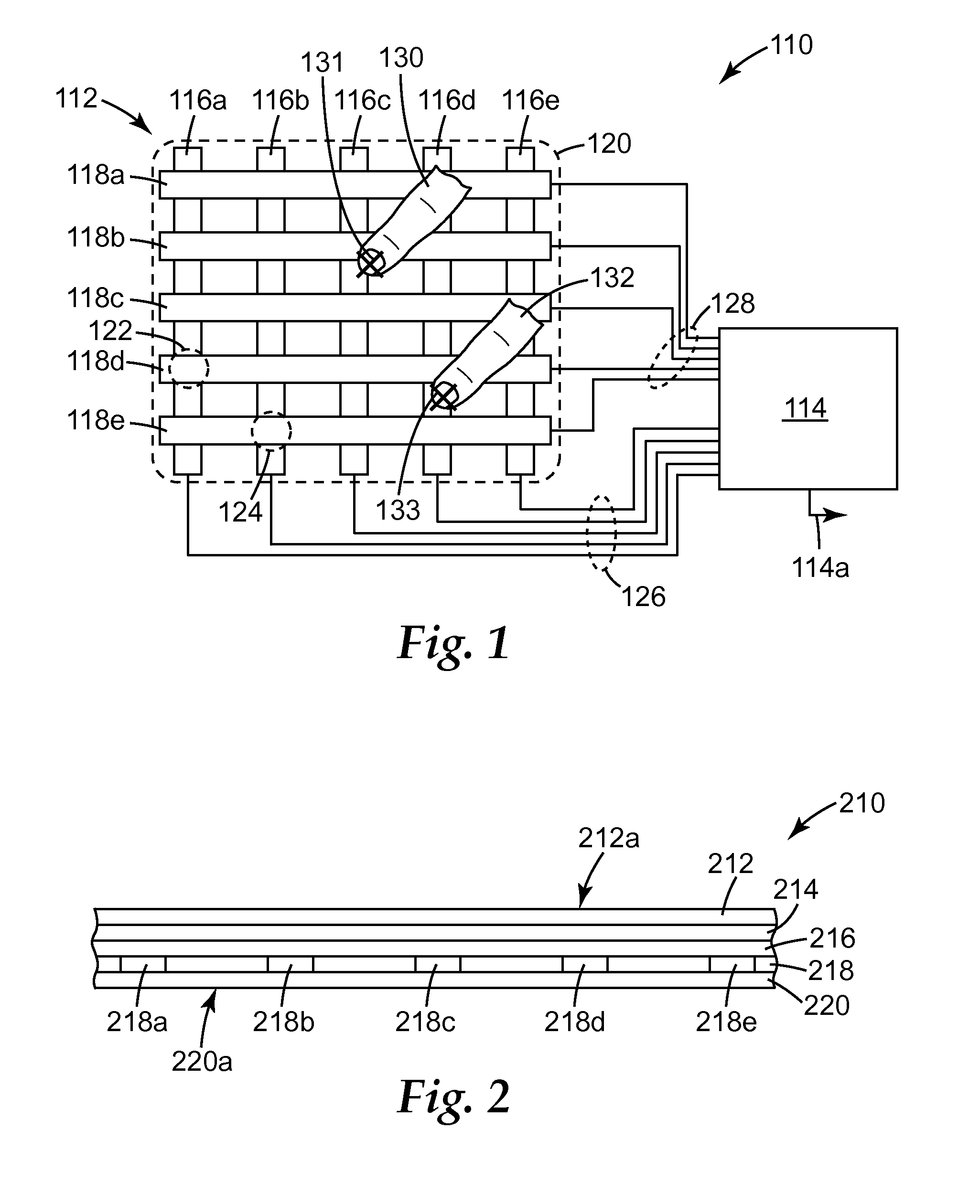
[0028]In FIG. 1, an exemplary touch device 110 is shown. The device 110 includes a touch panel 112 connected to electronic circuitry, which for simplicity is grouped together into a single schematic box labeled 114 and referred to collectively as a controller.

[0029]The touch panel 112 is shown as having a 5×5 matrix of column electrodes 116a-e and row electrodes 118a-e, but other numbers of electrodes and other matrix sizes can also be used. The panel 112 is typically substantially transparent so that the user is able to view an object, such as the pixilated display of a computer, hand-held device, mobile phone, or other peripheral device, through the panel 112. The boundary 120 represents the viewing area of the panel 112 and also preferably the viewing area of such a display, if used. The electrodes 116a-e, 118a-e are spatially distributed, from a plan view perspective, over the viewing area 120. For ease of illustration the electrodes are shown to be wide and obtrusive, but in pr...


PUM


Abstract

A touch-sensitive device includes a touch panel, drive unit, and measurement unit. A touch applied to a given node of the panel changes a capacitive coupling between a given drive and sense electrode of the touch panel. The drive unit delivers first and second drive signals, having different first and second frequencies, to first and second drive electrodes respectively at the same or overlapping times. The measurement unit receives a first response signal from a sense electrode, and analyzes the signal using maximum likelihood estimation to determine the coupling capacitance between the first drive electrode and the sense electrode, and between the second drive electrode and the sense electrode. More drive electrodes, including in some cases all the drive electrodes, can be driven with unique drive frequencies, and more sense electrodes, including in some cases all the sense electrodes, can be sensed by the measurement unit.

Description

FIELD OF THE INVENTION[0001]This invention relates generally to touch-sensitive devices, particularly those that rely on a capacitive coupling between a user's finger or other touch implement and the touch device, with particular application to such devices that are capable of detecting multiple touches applied to different portions of the touch device at the same time.BACKGROUND[0002]Touch-sensitive devices allow a user to conveniently interface with electronic systems and displays by reducing or eliminating the need for mechanical buttons, keypads, keyboards, and pointing devices. For example, a user can carry out a complicated sequence of instructions by simply touching an on-display touch screen at a location identified by an icon.[0003]There are several types of technologies for implementing a touch-sensitive device including, for example, resistive, infrared, capacitive, surface acoustic wave, electromagnetic, near field imaging, etc. Capacitive touch-sensing devices have been...

Claims


Application Information

Patent Timeline
IPC IPC(8): H03M1/22
CPCG06F3/044G06F3/04182G06F3/0445G06F3/0446G06F3/04166
Inventor MARINO, RACHAEL P.PETERSON, JR., RICHARD A.
Owner 3M INNOVATIVE PROPERTIES CO
Why Eureka
Try Eureka