Handheld device and disposition method of planar antenna
- Summary
- Abstract
- Description
- Claims
- Application Information
AI Technical Summary
Benefits of technology
Problems solved by technology
Method used
Image

Examples
first embodiment
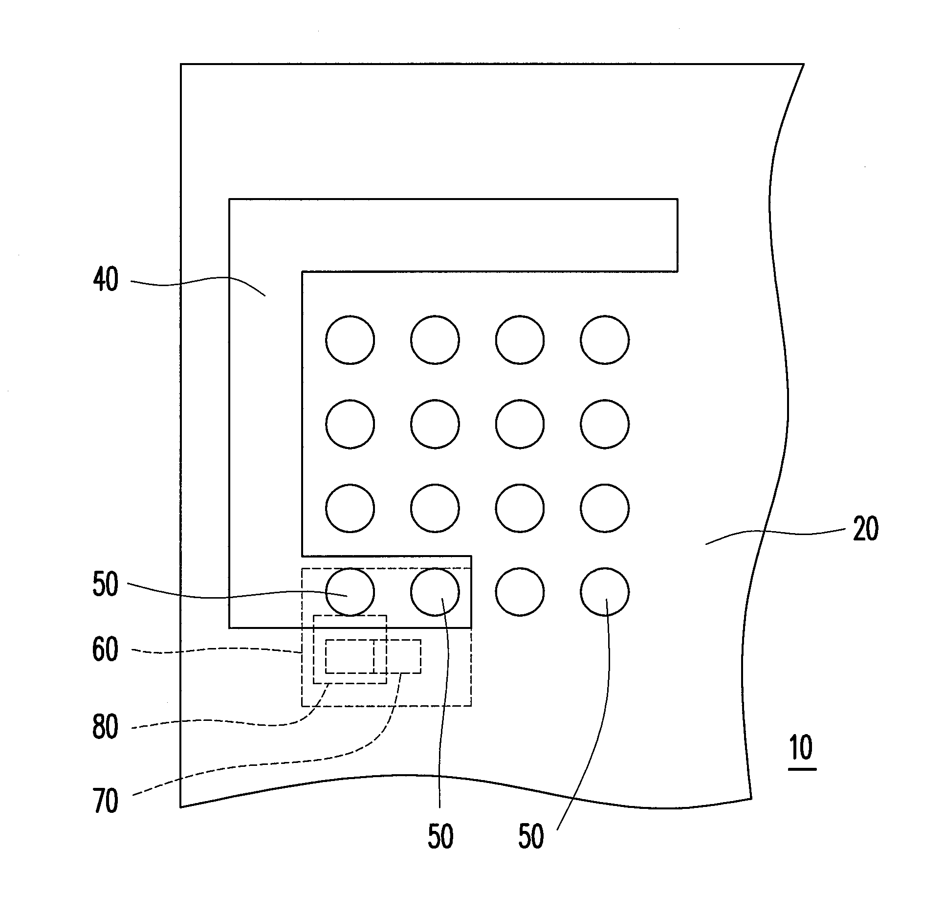
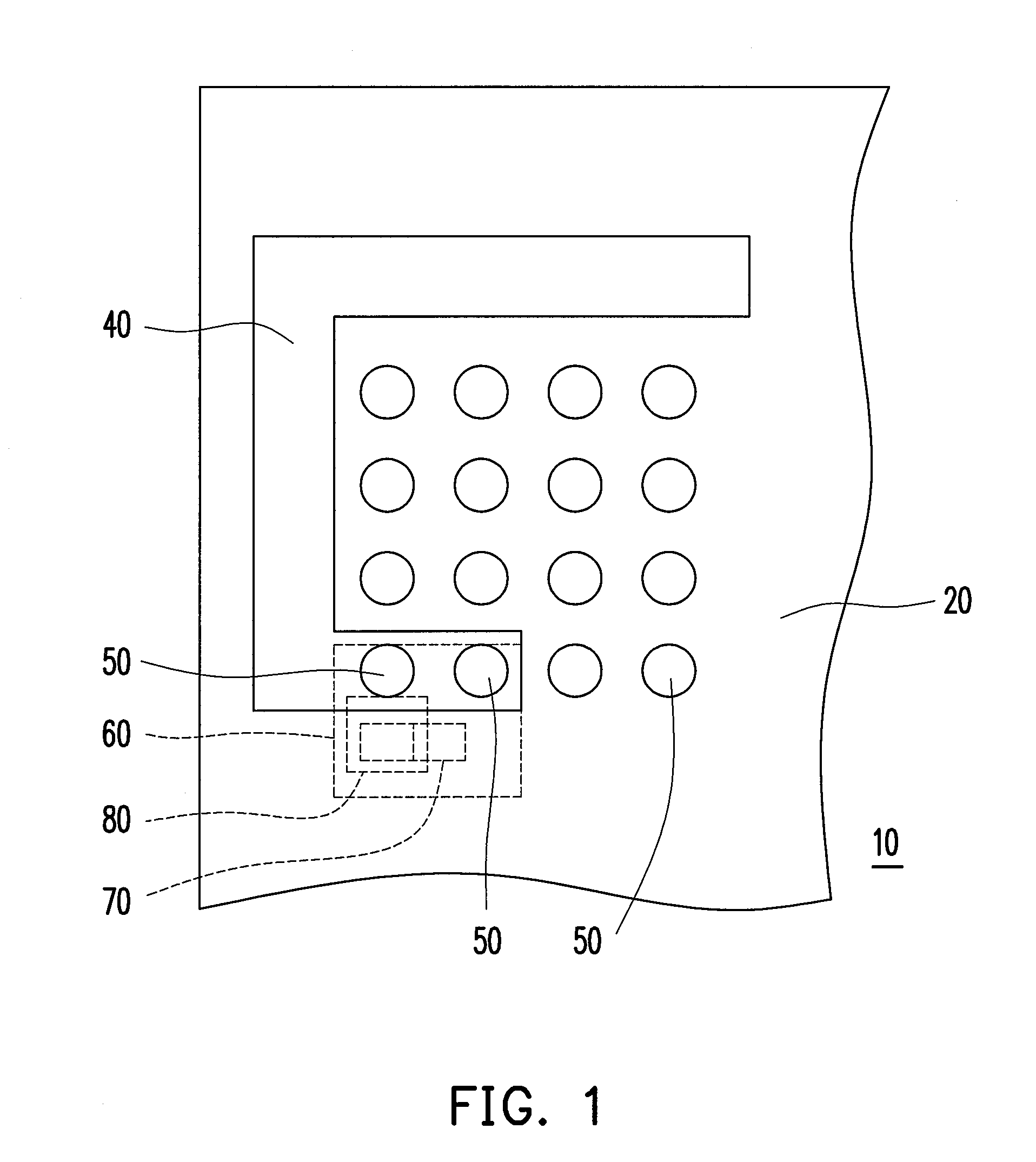
[0031]FIG. 1 is a top view of an appearance and a planar antenna according to the present invention, and FIG. 2 is a side view of the appearance and the planar antenna in FIG. 1. Referring to both FIG. 1 and FIG. 2, the handheld device 10 includes an appearance 20, a system ground plane 30, and a planar antenna 40. In the present embodiment, the handheld device 10 is a mobile phone. However, the present invention is not limited thereto.
[0032]The appearance 20 is described as a sound hole cover of a speaker. However, the present invention is not limited thereto. The appearance 20 has a plurality of vias 50. In the present embodiment, there are sixteen vias 50, and in other embodiments, there may also be one or other numbers of vias 50. Further, those vias can be arranged randomly, and the present embodiment is not limited to the rectangular pattern. In the present embodiment, the vias 50 are conductive vias, and which can not only be used for electrically connecting the planar antenn...
fourth embodiment
[0042]In addition, the shape of the planar antenna can be altered by those skilled in the art to allow the planar antenna to present a more meaningful or aesthetic pattern. FIG. 5 is a top view of an appearance and a planar antenna according to the present invention. The handheld device 13 illustrated in FIG. 5 is similar to the handheld device 10 illustrated in FIG. 1, and the difference between the two embodiments falls on the shapes of the planar antenna 40 and the planar antenna 41. In the present embodiment, the planar antenna 41 is designed to have a C shape. However, the subject application is not limited thereto, and in other embodiments, the planar antenna may also be designed into other patterns by those skilled in the art according to the actual requirements.
fifth embodiment
[0043]Moreover, the pattern of the planar antenna may also be decorated by those skilled in the art by using paint of different color. FIG. 6 is a top view of an appearance and a planar antenna according to the present invention. In the handheld device 14 provided by the present embodiment, the pattern of the planar antenna 40 is decorated by using a coating material (for example, paint) of different color. To be specific, the pattern of the planar antenna 40 can be extended by using a coating material 100, wherein the color of the coating material 100 is similar to the color of the planar antenna 40. In addition, the pattern of the planar antenna 40 may also be covered by using a coating material 101, wherein the color of the coating material 101 is similar to the color of the appearance 20.
[0044]FIG. 7 is a top view of the appearance and the planar antenna in FIG. 6 after they are painted. After the planar antenna 40 is decorated by using the coating materials 100 and 101, the pla...
PUM
 Abstract
Description
Claims
Application Information
 - R&D
- Intellectual Property
- Life Sciences
- Materials
- Tech Scout
- Unparalleled Data Quality
- Higher Quality Content
- 60% Fewer Hallucinations
Browse by: Latest US Patents, China's latest patents, Technical Efficacy Thesaurus, Application Domain, Technology Topic, Popular Technical Reports.
© 2025 PatSnap. All rights reserved.Legal|Privacy policy|Modern Slavery Act Transparency Statement|Sitemap|About US| Contact US: help@patsnap.com