Vehicle light

a technology for vehicles and light sources, applied in semiconductor devices, light sources, transportation and packaging, etc., can solve the problems of cost reduction and hinder the mass production of light sources, and achieve the effects of less color shading, less color shading, and suppressing the occurrence of color shading

Active Publication Date: 2011-04-14
SEOUL SEMICONDUCTOR +1
View PDF5 Cites 55 Cited by
  • Summary
  • Abstract
  • Description
  • Claims
  • Application Information

AI Technical Summary

Benefits of technology

According to the presently disclosed subject matter, the LED light source having a light emitting diode and a wavelength conversion material can emit light with less color shading at the edge of the light emitting surface of the LED light source, thereby suppressing the occurrence of the color shading of the illumination light.
Accordingly, a vehicle light made in accordance with the principles of the presently disclosed subject matter can have an LED light source and a light guide for projecting the light beams passing therethrough to form a desired light distribution pattern with the light guide being a lens body having an inner reflecting surface. The vehicle light can reduce the color shading of illumination light due to the color shading of the LED light source by the light distribution control by the light guide. As a result, the illumination light can be formed with less color shading while maintaining favorable color rendering properties under alleviated managing conditions with regard to the color shading of the light source. Furthermore, this configuration can improve the yield of mass production of the vehicle light with reduced cost.

Problems solved by technology

However, this may hinder the mass production of light sources and also prevent cost reduction.

Method used


Image

  • Vehicle light
  • Vehicle light
  • Vehicle light

Examples


Embodiment Construction

A description will now be made below to exemplary vehicle lights made in accordance with principles of the presently disclosed subject matter with reference to the accompanying drawings and in accordance with exemplary embodiments.

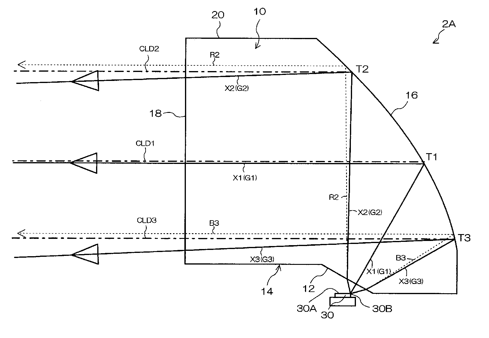
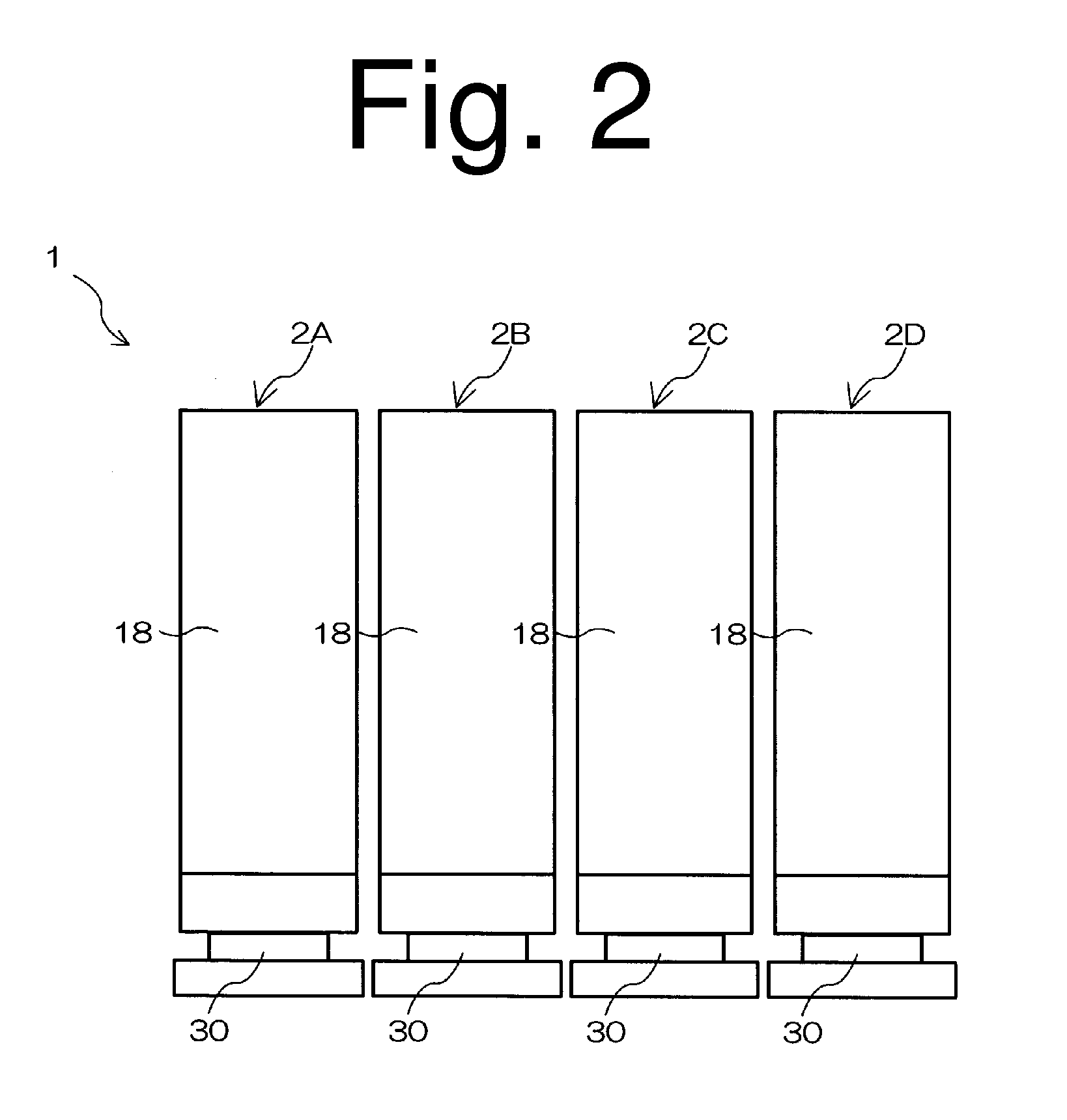
FIG. 2 is a front view of a vehicle light 1 made in accordance with principles of the presently disclosed subject matter. The vehicle light 1 can be employed, for example, as a headlight for a low beam for use in an automobile, a motorcycle, other vehicle, and the like and can include a plurality of (four in the illustrated example) light source units 2A, 2B, 2C, and 2D. Each light source unit can include an LED light source and a lens body serving as a light guide. The light source units 2A, 2B, 2C, and 2D can, for example, have the same configuration, but emit light beams with different light distribution sub-patterns. The illumination light emitted from the respective light source units 2A, 2B, 2C, and 2D through each respective light exiting surface of...


PUM


Abstract

A vehicle light can include a light emitting diode (LED) serving as a light source and an optical system for controlling a light distribution pattern of the light beams from the LED light source utilizing a light guide (such as a lens body having an inner reflecting surface). The vehicle light can project illumination light with a low beam light distribution pattern. The vehicle light can include an LED light source and a lens body serving as a light guide. The lens body can include a light incident surface, a reflecting surface, and a light exiting surface. The LED light source can have a rearmost end light emitting point from which light beams are emitted to form a bright-dark boundary line. Among the light beams, perpendicularly incident light beams not subjected to refraction can be projected toward the bright-dark boundary line while obliquely incident light beams that are subjected to refraction can be corrected to be directed in a lower angular direction than the bright-dark boundary line and to be mixed with the other light beams, thereby preventing color shading of illumination light from the vehicle light.

Description

This application claims the priority benefit under 35 U.S.C. §119 of Japanese Patent Application No. 2009-234436 filed on Oct. 8, 2009, which is hereby incorporated in its entirety by reference. This application is also related to and incorporates by reference the U.S. patent application entitled Vehicle Light filed on same date, Oct. 8, 2010, and assigned to the same entity and filed as attorney docket number ST3001-0269.TECHNICAL FIELDThe presently disclosed subject matter relates to a vehicle light, and in particular, relates to a vehicle light having a light emitting diode (LED) serving as a light source and an optical system for controlling light distribution pattern of the light beams from the LED light source utilizing a light guide (being a lens body having an inner reflecting surface), thereby projecting illumination light with a low-beam light distribution pattern, for example.BACKGROUND ARTJapanese Patent Application Laid-Open No. 2008-078086 discloses a vehicle light hav...

Claims


Application Information

Patent Timeline
Patent Type & Authority Applications(United States)
IPC IPC(8): F21V11/00F21V7/00
CPCF21S48/1159F21S48/1163F21Y2101/02F21V5/04F21V7/0091F21S48/1241F21S41/143F21S41/148F21S41/151F21S41/155F21S41/24F21Y2115/10
Inventor OHNO, MASAFUMIOWADA, RYOTAROMYOJIN, NORIKATSUYAMADA, MITSUOKITA, YASUSHISAKAI, SATOSHI
Owner SEOUL SEMICONDUCTOR
Why Eureka
Try Eureka