Coffee brewing system

Inactive Publication Date: 2011-04-21
GRINDMASTER CORP
View PDF10 Cites 5 Cited by
  • Summary
  • Abstract
  • Description
  • Claims
  • Application Information

AI Technical Summary

Benefits of technology

[0008]The present invention is a coffee brewing system that allows greater control over the quality of the coffee, makes it easier to brew coffee in a consistent manner, while also addressing other problems of prior urn constructions.
[0010]The heating elements in the interior cavity of the housing are “staggered,” with a respective heating element positioned near each liner, in an effort to maintain a consistent water temperature. By staggering the heating elements and positioning each heating element near a respective liner, consistent and optimal brewed coffee temperatures can be maintained at each liner.
[0013]With respect to each spray arm assembly, a downwardly extending bracket is also secured to each spray arm assembly. This bracket pivots with the pivoting of the spray arm assembly, and will engage left and right stops at the base of the spray arm assembly to prevent over-rotation of the spray arm assembly. Furthermore, a magnet is preferably secured near the distal end of this bracket. A magnetic proximity sensor assembly is located near each spray arm assembly. This magnetic proximity sensor assembly can provide information as to the position of the spray arm assembly by sensing the relative position of the magnet.
[0017]As a further refinement, an exemplary coffee brewing system made in accordance with the present invention may also include brew baskets that can accommodate different amounts of coffee grounds, depending on the amount of brewed coffee to be made. For example, if it is desirable to brew a smaller batch of coffee, an insert may be received in the brew basket. The filter and coffee grounds are placed in this insert, and so the same coffee brewing system can be used to brew the smaller batch of coffee without any degradation in quality.

Problems solved by technology

However, there are various problems with prior urn constructions.
For example, prior urn constructions often do not allow for much control over the water delivery, which can lead to an imprecise volume of water being delivered from the spray arm over the coffee grounds.
Alternatively, to the extent that the spray arm can be pivoted into and out of position over the coffee grounds, there is the possibility of water spillage when the spray arm is not properly positioned over the brew basket.
Such differences in temperature can lead to quality differences with respect to the brewed coffee.
However, placing a smaller amount of coffee grounds in a brew basket designed for larger quantities will cause the layer of coffee grounds in the brew basket to be too thin and will cause the coffee grounds to be over-extracted.
Furthermore, prior urn constructions do not compensate for the shorter brew time required in brewing a smaller batch of coffee, such as a half batch.
Rather, in prior art constructions, brewing a half batch of coffee violated industry coffee brewing standards with respect to the required contact time between the coffee grounds and the hot water.
The shorter contact time in a half batches of coffee again produces a coffee that is not properly extracted and will often be of poor quality.
For yet another example, the sight glasses used in prior urn constructions are often fragile and also difficult to read when residue accumulates on the sight glass.
Residue from the sight glass can also contaminate future batches of coffee, and when using a sight glass, the temperature of the coffee is lowered because a portion of the coffee that is poured out into each cup comes from the portion of coffee in the sight glass.

Method used


Image

  • Coffee brewing system
  • Coffee brewing system
  • Coffee brewing system

Examples


Embodiment Construction

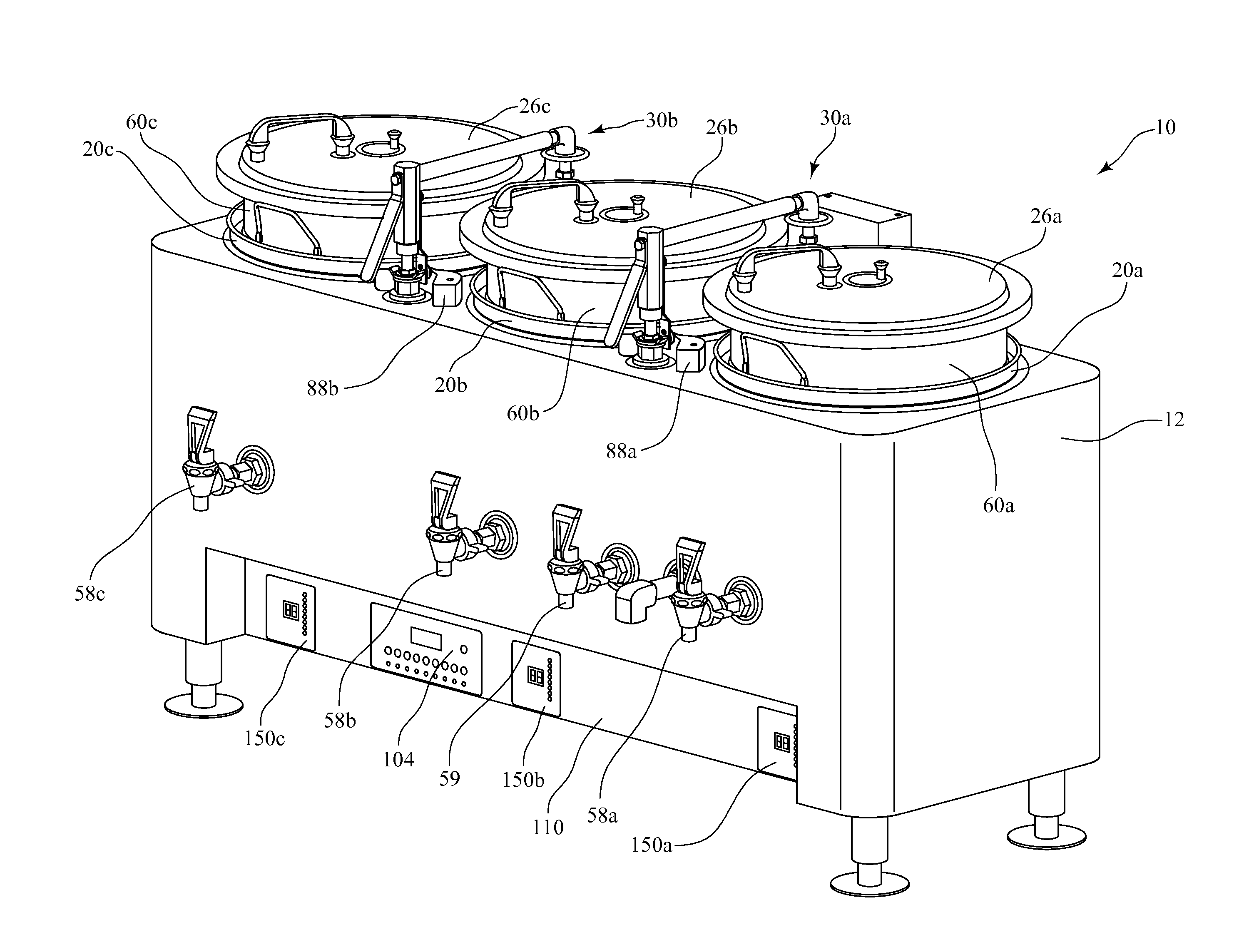
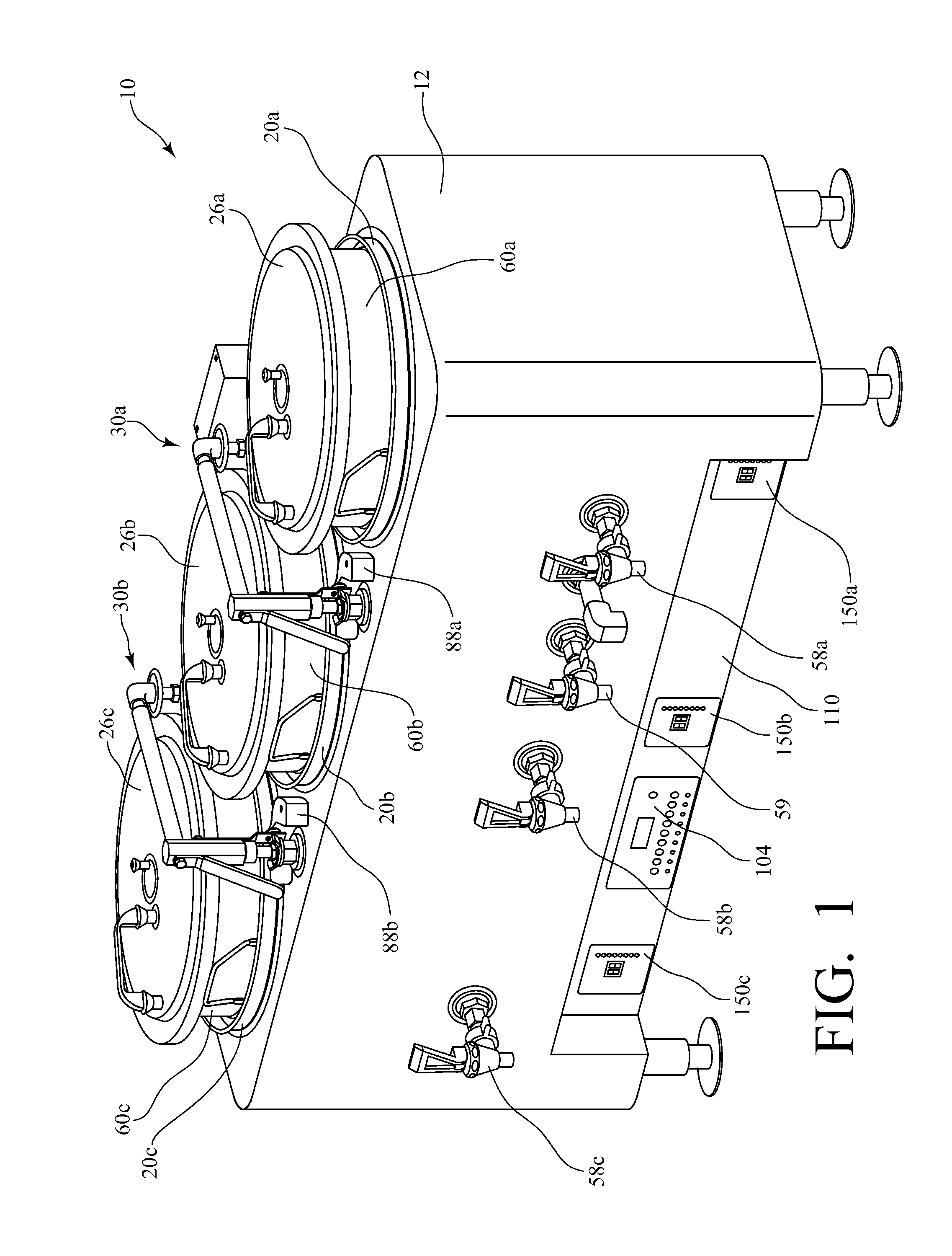
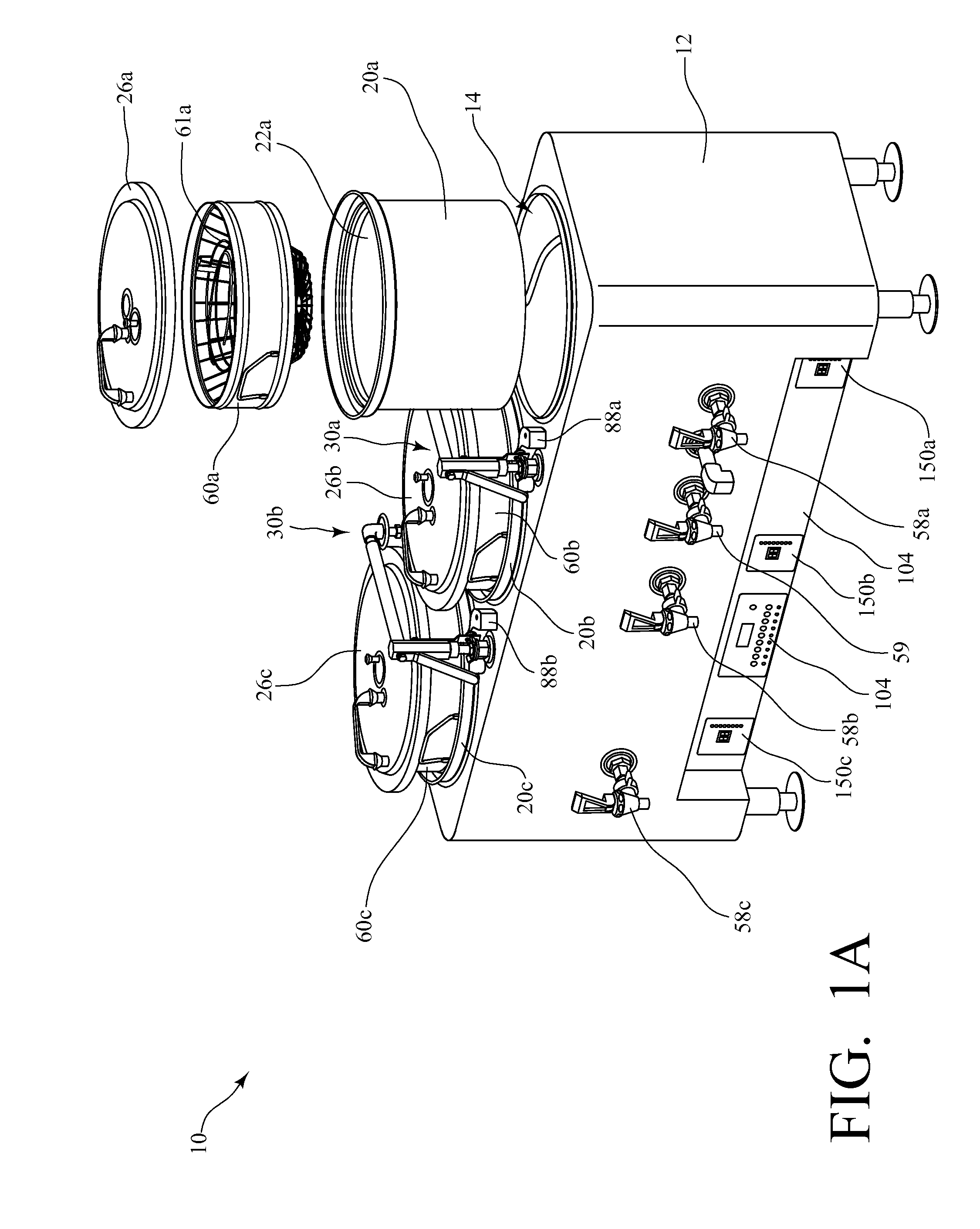
[0036]FIGS. 1-5 are various views of an exemplary coffee brewing system 10 made in accordance with the present invention. The coffee brewing system 10 of the present invention may also be referred to as an “urn.” In the exemplary embodiment shown in FIGS. 1-5, the urn 10 includes: a housing 12 that defines an interior cavity 14 for storing a volume of water; a fill valve 116 for controlling flow of water into the interior cavity through an inlet pipe 16; heating elements 70a, 70b, 70c in the interior cavity 14 for heating the water; three liners 20a, 20b, 20c, each of which are housed within the interior cavity 14 and surrounded by the water, and each liner 20a, 20b, 20c having a generally cylindrical shape defining an internal volume 22a, 22b, 22c and an open end 24a, 24b, 24c; covers 26a, 26b, 26c for the respective liners 20a, 20b, 20c; two pivoting spray arm assemblies 30a, 30b for delivering water to the three liners 20a, 20b, 20c; three brew baskets 60a, 60b, 60c, each receive...


PUM


Abstract

A coffee brewing system comprises: a housing defining an interior cavity for storing a volume of water; a fill valve for controlling flow of water into the interior cavity through an inlet pipe; a plurality of liners housed within the interior cavity and surrounded by the water in the interior cavity; one or more heating elements positioned within the interior cavity to heat and maintain the temperature of the water; a plurality of brew baskets, each of which is received in one of the plurality of liners and configured for holding a quantity of coffee grounds; a plurality of pivoting spray arm assemblies, each said pivoting spray arm assembly configured for pivotal movement relative to the housing; one or more pumps, each said pump for conveying water from the interior cavity of the housing to a respective pivoting spray arm assembly, which then delivers the water to a selected brew basket for making brewed coffee; and a control system for controlling operation of each said pump, each said heating element, and said fill valve.

Description

CROSS-REFERENCE TO RELATED APPLICATIONS[0001]The present application claims priority to U.S. Provisional Patent Application Ser. No. 61 / 168,788 filed on Apr. 13, 2009, the entire disclosure of which is incorporated herein by reference.TECHNICAL FIELD[0002]The present invention is a coffee brewing system that allows greater control over the quality of the coffee, makes it easier to brew coffee in a consistent manner, while also addressing other problems of prior urn constructions.BACKGROUND OF THE INVENTION[0003]Various coffee brewing systems exist in the prior art in which brewed coffee is held in and dispensed from one or more liners. The exterior housing in such an “urn” construction defines an interior cavity for storing a volume of water, and there are heating elements in the interior cavity for heating the water. Each of the liners is then seated in a respective opening defined through the top surface of the housing, so that the liner is surrounded by the heated water. In makin...

Claims


Application Information

Patent Timeline
IPC IPC(8): A47J31/44A47J31/46A47J31/56A47J31/50
CPCA47J31/007A47J31/50A47J31/057
Inventor DAHMEN, WILLIAM ALEXISPFEIFER, THOMAS J.GANTT, TIMOTHY D.
Owner GRINDMASTER CORP
Why Eureka
Try Eureka