Solar cell and manufacturing method thereof

a technology of solar cells and manufacturing methods, applied in the field of solar cells, to achieve the effect of improving photoelectric conversion efficiency and reducing the chance of surface recombination

Inactive Publication Date: 2011-04-21
AURIA SOLAR CO LTD
View PDF7 Cites 19 Cited by
  • Summary
  • Abstract
  • Description
  • Claims
  • Application Information

AI Technical Summary

Benefits of technology

[0009]In view of this, the present invention provides a solar cell, which has an improved photo-electric conversion efficiency by reducing the chance of surface recombination of the electron-hole pairs.
[0011]The solar cell of the present invention comprises a substrate, a first conductive layer, a photovoltaic layer, a second conductive layer and at least one passivation layer. The first conductive layer is disposed on the substrate. The photovoltaic layer is adapted to generate electron-hole pairs when being irradiated by a light ray. The photovoltaic layer is disposed on the first conductive layer and has a plurality of doped films. The second conductive layer is disposed on the photovoltaic layer. The at least one passivation layer is disposed on at least one of the positions between the first conductive layer and the photovoltaic layer, between the doped films in the photovoltaic layer and between the photovoltaic layer and the second conductive layer, so as to reduce the chance of surface recombination of the electron-hole pairs on at least one surface of the photovoltaic layer.
[0027]The method for manufacturing a solar cell of the present invention comprises the following steps: providing a substrate; forming a first conductive layer on the substrate; forming, on the first conductive layer, a photovoltaic layer having a plurality of doped films, wherein the photovoltaic layer generates electron-hole pairs when being irradiated by a light ray; forming a second conductive layer on the photovoltaic layer; and forming a passivation layer on at least one of the positions between the first conductive layer and the photovoltaic layer, between the doped films in the photovoltaic layer and between the photovoltaic layer and the second conductive layer, so as to reduce the chance of surface recombination of the electron-hole pairs on at least one surface of the photovoltaic layer.
[0032]According to the above descriptions, the solar cell of the present invention has at least one passivation layer disposed on at least one of the positions between the first conductive layer and the photovoltaic layer, between the doped films in the photovoltaic layer and between the photovoltaic layer and the second conductive layer. This can reduce the chance of surface recombination of the electron-hole pairs to result in an improved photo-electric conversion efficiency of the solar cell. Furthermore, a method for manufacturing a solar cell is also disclosed in the present invention, with which the aforesaid solar cell can be manufactured.

Problems solved by technology

Currently, a critical problem related to solar cells is how to improve the photo-electric conversion efficiency thereof, and any improvement in the photo-electric conversion efficiency of solar cells will lead to improvement in competitive edge of the solar cell products.

Method used


Image

  • Solar cell and manufacturing method thereof
  • Solar cell and manufacturing method thereof
  • Solar cell and manufacturing method thereof

Examples


Embodiment Construction

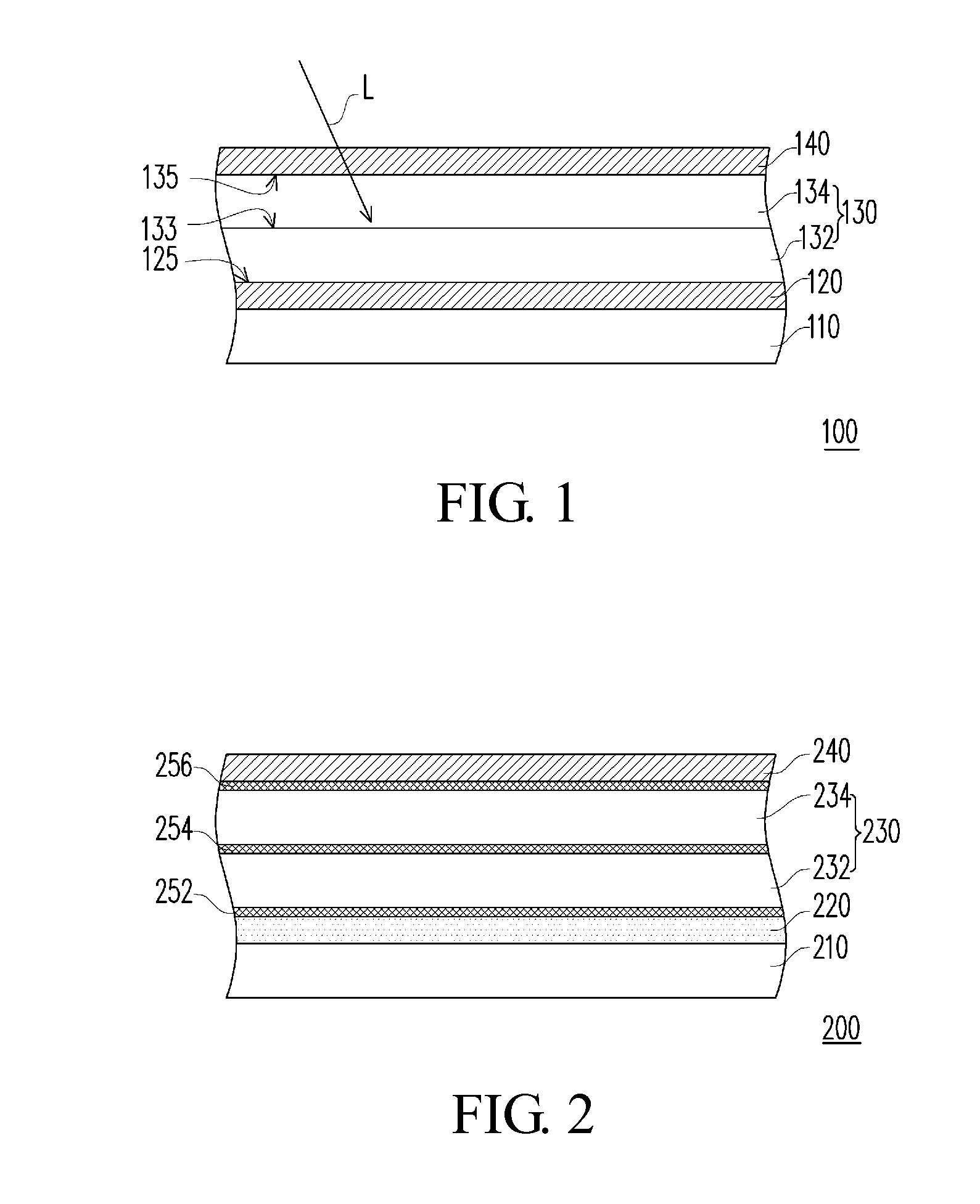
[0039]FIG. 2 is a schematic view of a solar cell according to an embodiment of the present invention. Referring to FIG. 2, the solar cell 200 comprises a substrate 210, a first conductive layer 220, a photovoltaic layer 230, a second conductive layer 240 and passivation layers 252, 254, 256. In this embodiment, the substrate 210 is, for example, a transparent substrate such as a glass substrate.

[0040]The first conductive layer 220 is disposed on the substrate 210. In this embodiment, the first conductive layer 220 is a transparent conductive layer, which may be made of at least one of zinc oxide, tin oxide, indium tin oxide (ITO), indium zinc oxide (IZO), indium tin zinc oxide (ITZO), aluminum tin oxide (ATO), aluminum zinc oxide (AZO), cadmium indium oxide (CIO), cadmium zinc oxide (CZO), gallium zinc oxide (GaZO) and tin oxyfluoride.

[0041]The photovoltaic layer 230 generates electron-hole pairs when being irradiated by a light ray. The photovoltaic layer 230 is disposed on the fir...


PUM


Abstract

A solar cell including a substrate, a first conductive layer, a photovoltaic layer, a second conductive layer and at least one passivation layer is provided. The first conductive layer is disposed on the substrate. The photovoltaic layer generates electron-hole pairs after receiving light, wherein the photovoltaic layer is disposed on the first conductive layer and has a plurality of doped films. The second conductive layer is disposed on the photovoltaic layer. The passivation layer is disposed onto at least one of the positions between the first conductive layer and the photovoltaic layer, between the doped films within the photovoltaic layer, and between the photovoltaic layer and the second conductive layer, so as to reduce the chance for the electron-hole pairs resulting in recombination on at least one of the surfaces of the photovoltaic layer. A manufacturing method of the solar cell is also provided.

Description

CROSS-REFERENCES TO RELATED APPLICATIONS[0001]This application claims priority to Taiwan Patent Application No. 098145634 filed on Dec. 29, 2009, which is hereby incorporated by reference in its entirety.BACKGROUND OF THE INVENTION[0002]1. Field of the Invention[0003]The present invention relates to a solar cell and a manufacturing method thereof, and more particularly, to a solar cell with an improved photo-electric conversion efficiency and a manufacturing method thereof.[0004]2. Descriptions of the Related Art[0005]With rising of the environmental protection awareness, the concept of “energy saving and carbon dioxide emission reduction” is gradually receiving more and more attention. Accordingly, exploitation and use of renewable energy sources have become a focus of development all over the world. Among the renewable energy sources, solar cells that are capable of converting the solar energy into the electric energy are considered to be the most promising, so numerous manufactur...

Claims


Application Information

Patent Timeline
Patent Type & Authority Applications(United States)
IPC IPC(8): H01L31/06H01L31/18
CPCH01L31/02167H01L31/0392H01L31/056Y02E10/52H01L31/1868H01L31/03923H01L31/03925Y02E10/541Y02P70/50
Inventor TSAI, CHIN-YAO
Owner AURIA SOLAR CO LTD
Why Eureka
Try Eureka