Short and ultra-short baseline phase maps

a baseline and phase map technology, applied in satellite radio beaconing, measurement devices, instruments, etc., can solve the problems of affecting the reception of signals, the proximity of the antenna, and the adverse effects of the fixed baseline system, and achieve the effect of greater accuracy

Active Publication Date: 2011-04-21
NOVATEL INC
View PDF11 Cites 22 Cited by
  • Summary
  • Abstract
  • Description
  • Claims
  • Application Information

AI Technical Summary

Benefits of technology

[0009]A short or ultra-short baseline system generates a corresponding phase map or table that associates carrier phase difference errors with the angles of incidence or arrival of the incoming GNSS satellites signals at the rover receiver antennas. The short baseline look-up mechanism provides compensating carrier phase difference corrections that are used in azimuth determination, to correct for phase distortions associated with multipath signals at the respective antennas and line biases associated with receiver operations. The ultra-short baseline phase map provides compensating carrier phase difference corrections that further correct for local Radio Frequency (RF) effects between the two closely spaced antennas on the ultra-short baseline.
[0010]The system generates the phase map and / or an associated phase difference error lookup table based on both expected phase differences and measured phase differences at the rover receiver antennas for GNSS satellite signals at respective angles of incidence. The system determines map grid sizes based on a gradient of the phase difference errors, with smaller grid sizes used for higher gradients. The grid size may also depend on user application accuracy requirements, with smaller grid sizes utilized with greater accuracy requirements. Alternatively, or in addition, multi-parameter mathematical models, such as spherical models, may be used to represent the difference errors instead of a lookup table. The phase map, lookup table and / or mathematical model are also referred to herein collectively as a “look-up mechanism.”

Problems solved by technology

The fixed baseline systems suffer from the adverse effects of multipath and biases introduced by receiver operations.
However, the close proximity of the antennas may adversely affect the received signals due, for example, to cross-talk between the antennas.

Method used


Image

  • Short and ultra-short baseline phase maps
  • Short and ultra-short baseline phase maps
  • Short and ultra-short baseline phase maps

Examples


Embodiment Construction

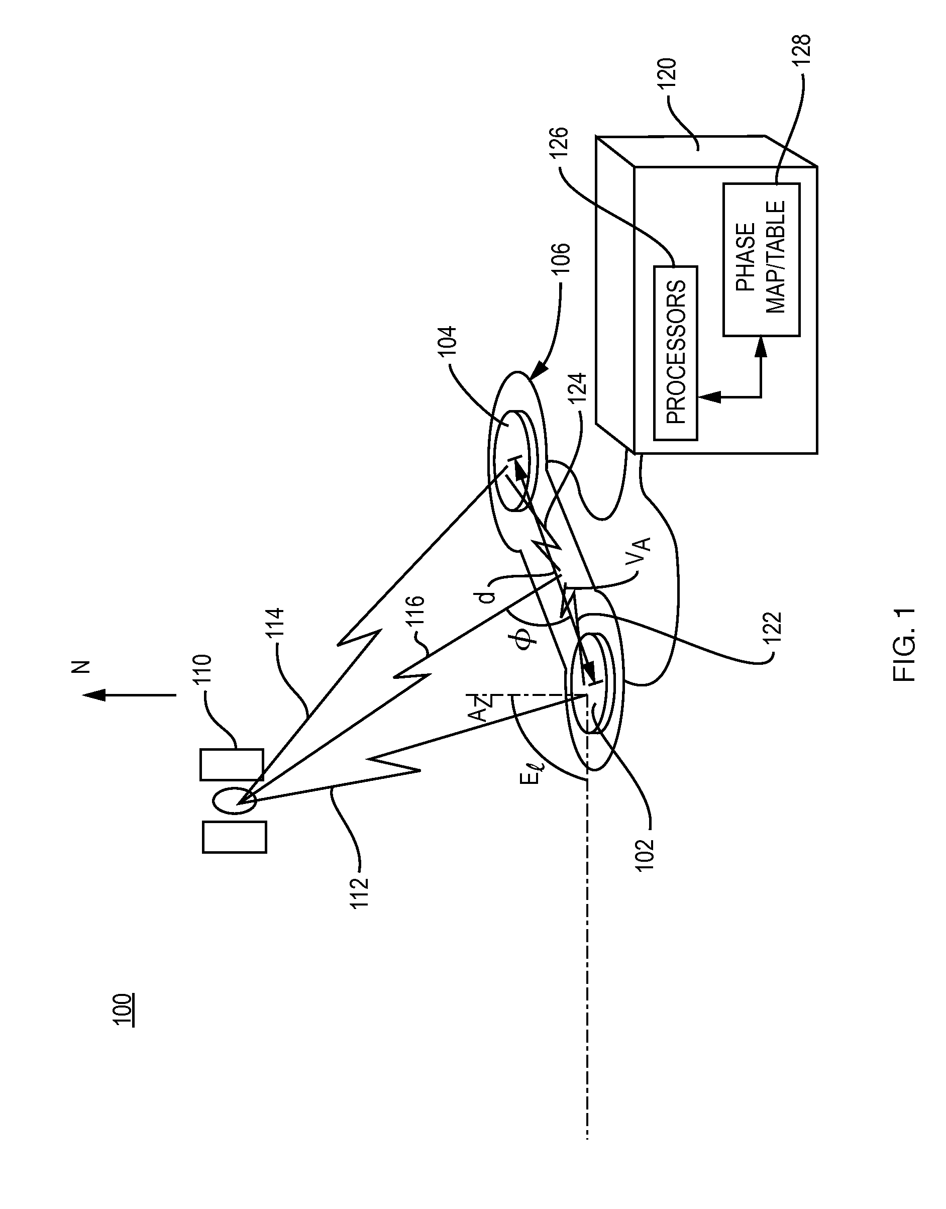
[0017]FIG. 1 is a schematic illustration of a short baseline receiver 120 that receives GNSS satellite signals transmitted by a GNSS satellite 110, in accordance with an illustrative embodiment of the present invention. More specifically, the system 100 of FIG. 1 includes dual antennas 102 and 104 that are shown mounted on a rigid frame 106. The antennas reside a relatively short distance apart, as illustrated by the dimension “d.” The operations of the system are described for the dimension d greater than one wavelength of the GNSS signal and also for the dimension d less than one wavelength of the GNSS signal. Further, an array of more than two antennas may be utilized with each antenna a distance d from its neighbors. For ease of explanation the system is described as utilizing the dual antennas.

[0018]The GNSS satellite signal is represented schematically as signal path 112, which is received by antenna 102, and signal path 114, which is received by antenna 104. The lengths of th...


PUM


Abstract

A system for generating and utilizing a look-up mechanism consisting of one or more phase difference error maps, tables and/or mathematical models calculates the respective maps, tables and/or models by placing a short baseline or ultra-short baseline antenna array in a known location and known orientation, determining angles of incidence of incoming GNSS satellite signals with respect the antenna array and calculating expected carrier phase differences between respective pairs of antennas, calculating measured carrier phase differences between the respective pairs of antennas, and determining carrier phase difference errors using the expected and measured carrier phase differences. The carrier phase difference errors are then recorded in the look-up mechanism, with the maps and, as appropriate, look-up tables for the respective pairs of antennas being indexed by angles of incidence. Thereafter, the system utilizes the look-up mechanism when determining the unknown orientation of the antenna structure. For respective pairs of antennas, the system enters the look-up mechanism based on angles of incidence determined from a calculated orientation, and uses the retrieved values in the calculation of a corrected orientation, to compensate for phase distortion.

Description

BACKGROUND OF THE INVENTION[0001]1. Field of the Invention[0002]This invention relates generally to global navigation satellite systems (GNSS) and more particularly to short baseline receivers.[0003]2. Background Information[0004]Short baseline real time kinematic (RTK) systems typically operate with a base GNSS receiver and a rover GNSS receiver that are separated by a small number of kilometers, for example, less than 10 kilometers. The base receiver, which is in a known position, makes carrier phase measurements using GNSS signals transmitted from GNSS satellites in view and calculates pseudoranges from the respective satellites. The base receiver then determines differences between the pseudoranges calculated using the satellite signals and the ranges based on the known position of the receiver and the known locations of the satellites, to determine range correction information. The base receiver operating in a known manner broadcasts the RTK information, that is, the range corr...

Claims


Application Information

Patent Timeline
Patent Type & Authority Applications(United States)
IPC IPC(8): G01S19/53G01S19/29
CPCG01S19/54G01S19/23G01S19/22
Inventor FENTON, PATRICK C.
Owner NOVATEL INC
Why Eureka
Try Eureka