Maintenance system of helical turbine

a helical turbine and maintenance system technology, applied in the field of assembled helical turbine systems, can solve the problems of difficult assembly of the housing assembly and sea water pollution, and achieve the effects of shortening the construction period of the assembled helical turbine system, improving the workability of the assembly/disassembly process, and easy assembly/disassembly of the housing assembly

Inactive Publication Date: 2011-04-21
KOREAN OCEAN RES & DEV INST KORDI
View PDF3 Cites 12 Cited by
  • Summary
  • Abstract
  • Description
  • Claims
  • Application Information

AI Technical Summary

Benefits of technology

[0011]An assembled helical turbine system according to the present invention makes it possible to easily assemble / disassemble a housing assembly with a helical turbine assembly fixed therein without being hindered by a rotational force that is generated by the flow of the tidal currents, thereby improving the workability of the assembly / disassembly process and shortening the construction period of the assembled helical turbine system.

Problems solved by technology

However, since the conventional tidal power generation is driven using potential energy, it requires a water level above a certain height.
To this end, it is requisite to build a seawall, which is accompanied by environmental problems including sea water pollution.
In the conventional helical turbine generator having the above structure, however, there is a problem in that when the housing assembly 140 supporting the helical turbine 130 is assembled in the inner space of the housing supporter 110, a rotational force continuously acts on the helical turbine 130 due to fluid flow, even during the assembly process, and consequently the housing assembly 140 is rotated in the inner space of the housing supporter 110 by the force applied to the helical turbine 130, which makes it difficult to assemble the housing assembly 140.

Method used


Image

  • Maintenance system of helical turbine
  • Maintenance system of helical turbine
  • Maintenance system of helical turbine

Examples


Embodiment Construction

[0018]Hereinafter, a first preferred embodiment of an assembled helical turbine system according to the present invention will be described in detail with reference to the accompanying drawings. In the following description, the same parts as those of the conventional structure will be designated by the same reference numerals

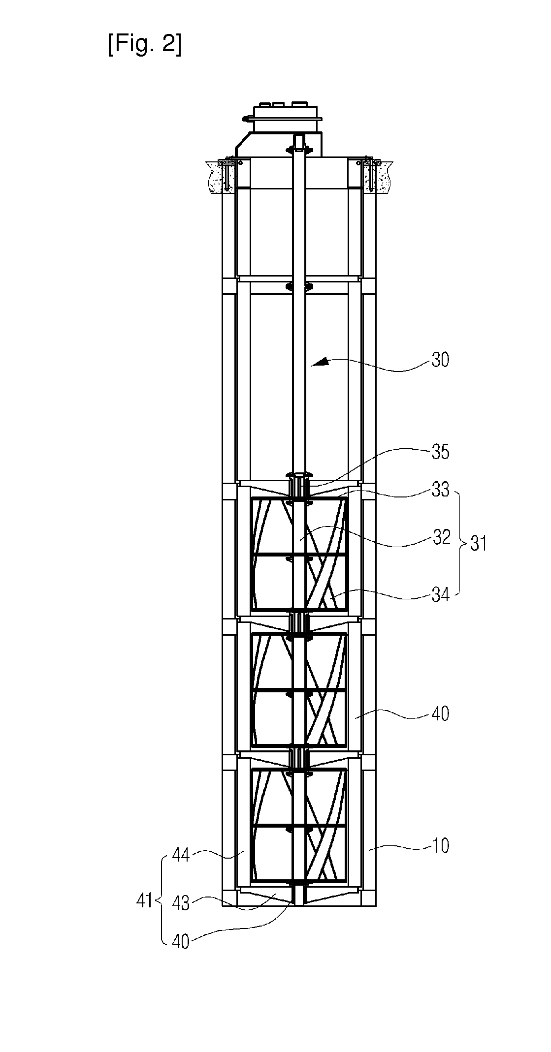
[0019]FIG. 2 illustrates in section an assembled helical turbine system according to a first preferred embodiment of the present invention, FIG. 3 illustrates a perspective view of the helical turbine system in FIG. 2, and FIG. 4 illustrates a plan view of the helical turbine system in FIG. 2.

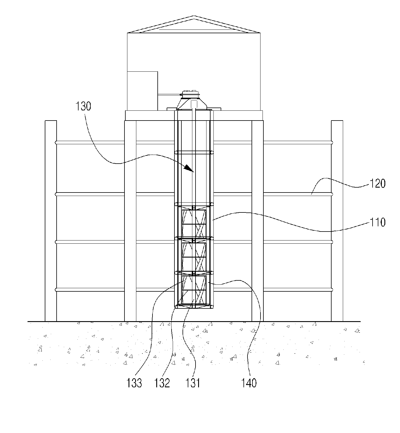
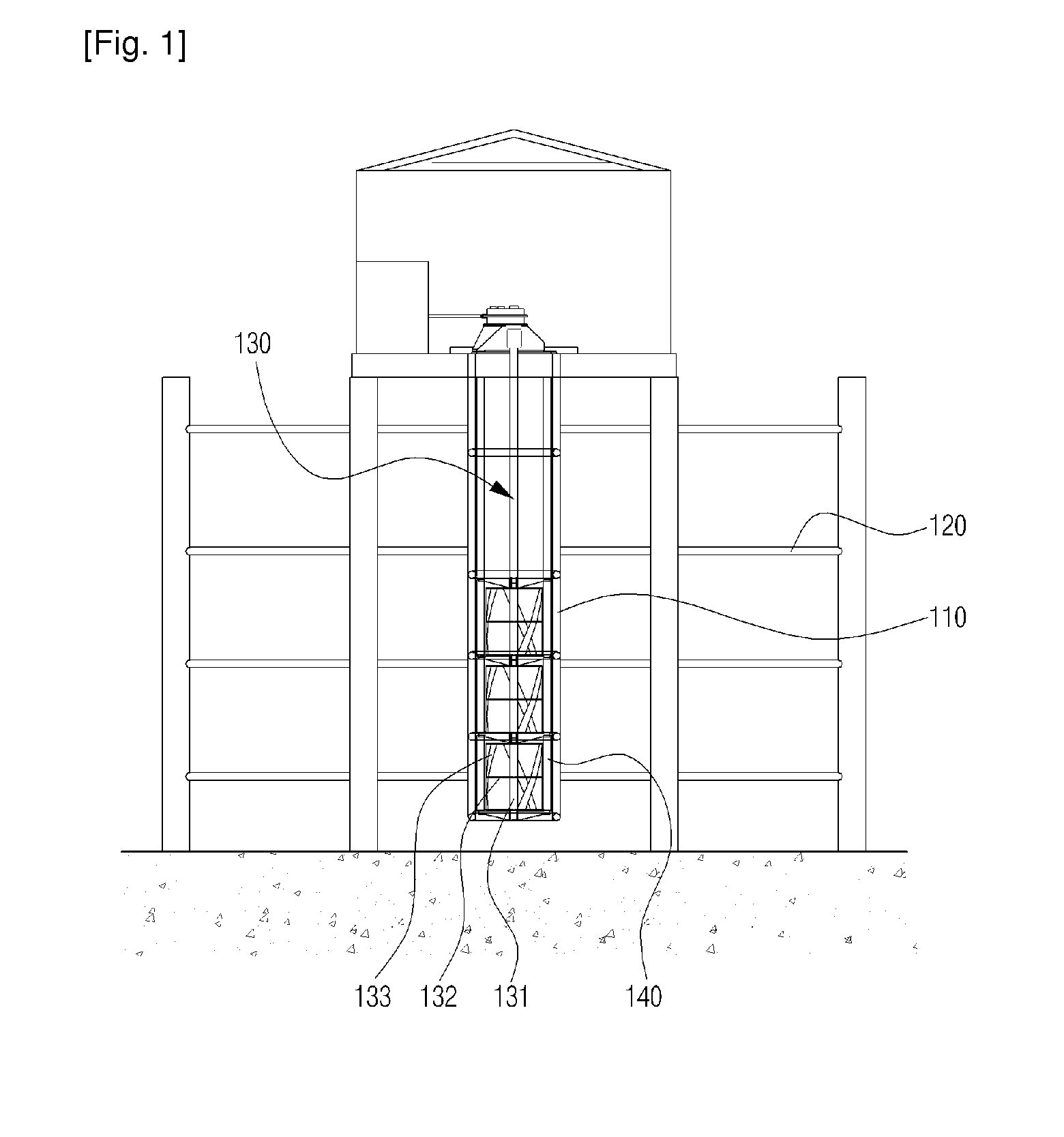
[0020]As illustrated in the drawings, the assembled helical turbine system according to this embodiment includes a frame 120 dipped in fluid, a housing supporter 10 provided in the frame 120, and a housing assembly 40 for rotatably mounting a helical turbine assembly 30 in its central portion, the housing assembly 40 being inserted in the housing supporter 10.

[0021]The hel...


PUM


Abstract

Disclosed is an assembled helical turbine system, which can prevent its assembly / disassembly from being hindered by a rotational force generated during the assembly / disassembly process. The assembled helical turbine system includes a helical turbine formed with a plurality of blades in such a manner as to continuously generate a rotational force under unidirectional or multidirectional fluid flow; a housing assembly for rotatably supporting the helical turbine while surrounding the helical turbine; stoppers formed on a peripheral surface of the housing assembly in such a manner as to protrude to a predetermined height from the peripheral surface; and a housing supporter for supporting the housing assembly in such a manner that the housing assembly can be inserted into and withdrawn from the housing supporter, the housing supporter having catch grooves that are recessed in a shape corresponding to the stoppers so as to fix the stoppers.

Description

TECHNICAL FIELD[0001]The present invention relates to an assembled helical turbine system, and more particularly to an assembled helical turbine system, in which when a housing assembly with a helical turbine fixed thereto is mounted in a housing supporter for supporting the housing assembly, the housing assembly can be easily assembled in the housing supporter without being hindered by rotation of the helical turbine, which is continuously generated by the flow of tidal currents.BACKGROUND ART[0002]In general, a turbine refers to a machine or an apparatus for converting energy included in fluid, such as water, gas, or steam, into useful mechanical work. An apparatus for generating energy by using such a turbine is mainly used in tidal power generation. In conventional tidal power generation, a tidal dam is built in a back bay with the, where there is a big difference between the ebb and flow of the tide to thereby interrupt the movement of sea water, and then electricity is generat...

Claims


Application Information

Patent Timeline
Patent Type & Authority Applications(United States)
IPC IPC(8): F04D3/02
CPCF03B11/00F03D1/001F03D11/04Y02E10/728F05B2230/70Y02E10/226F05B2230/60F03D13/20F03D13/10F03D80/70Y02E10/20Y02E10/72Y02P70/50F03B3/02F03B13/12
Inventor PARK, JIN SOONLEE, KWANG SOOYUM, KI DAIKIM, SEONG EUNOH, MYOUNG HAKLEE, CHOONG BEOMAN, HYUNG JIN
Owner KOREAN OCEAN RES & DEV INST KORDI
Why Eureka
Try Eureka