

Asymmetric Parabolic Compound Concentrator With Photovoltaic Cells
- Summary
- Abstract
- Description
- Claims
- Application Information
AI Technical Summary
Benefits of technology
Problems solved by technology
Method used
Image

Examples
Embodiment Construction
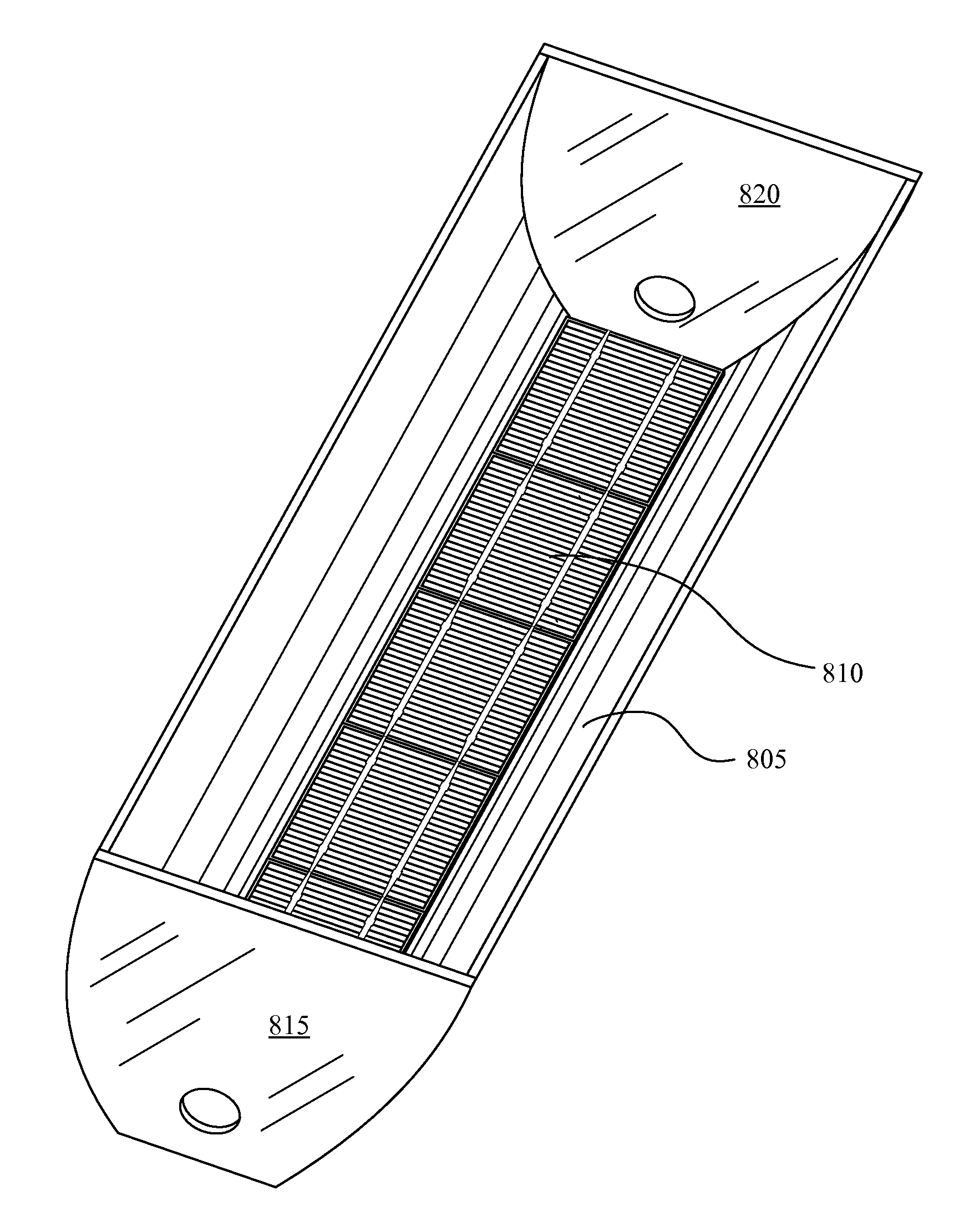
In some embodiments of the invention, an asymmetric compound parabolic concentrator (ACPC) is disclosed that may collect light and direct the light onto a photovoltaic cell. The combined device is an ACPC with a photovoltaic cell (ACPC-PV). The ACPC can collect light from the sun without the use of tracking devices despite seasonal variations in the sun's elevation. In some embodiments, an ACPC can be submerged in an liquid (e.g., water or some water solution) and / or coupled with a photovoltaic cell. In some embodiments, the liquid can be a combination of water with other substances such as glycerol or alcohols. When choosing a liquid, in some embodiments, the liquid can have a high specific heat for increased heat stabilization, a lower solar absorption to allow more solar light to pass through the liquid, and / or a high viscosity to reduce rippling at the surface.
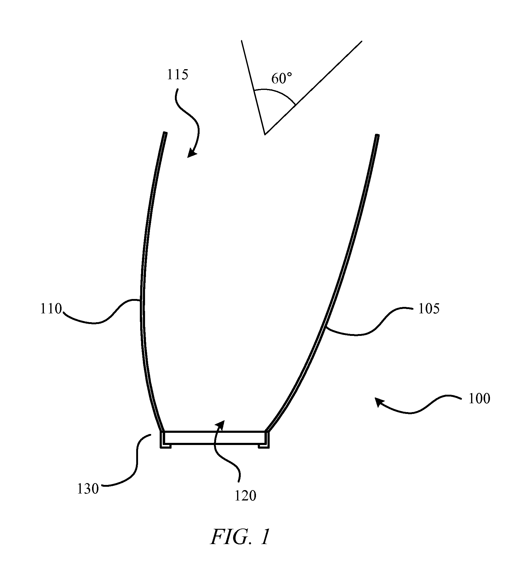
FIG. 1 shows ACPC 100 coupled with a photovoltaic cell 130 according to one embodiment of the invention. Photovoltaic ce...
PUM
| Property | Measurement | Unit |
|---|---|---|
| Angle | aaaaa | aaaaa |
| Angle | aaaaa | aaaaa |
| Shape | aaaaa | aaaaa |
Abstract
Description
Claims
Application Information