Lens Stack, Mounted in a Gas-Tight Manner, for a Camera Housing

a technology of lens stack and camera housing, which is applied in the field of camera modules, can solve the problems of dew formation in the optical path, degradation of image quality, and high mechanical stress on the camera module used in motor vehicle operation, and achieve the effect of shortening the tolerance chain and reducing the number of components

Active Publication Date: 2011-04-28
ROBERT BOSCH GMBH
View PDF20 Cites 6 Cited by
  • Summary
  • Abstract
  • Description
  • Claims
  • Application Information

AI Technical Summary

Benefits of technology

[0009]According to the present invention, a compact and impervious design of a camera suitable for use in motor vehicles is provided, which is minimized with regard to the number of mechanical components and the mechanical interfaces and in which, during the assembly, the image sensor is positioned relative to the objective lens with the aid of a mechanical adjusting device. The mechanical adjusting advice may be a hexapod, for instance, which is able to be guided very precisely within six degrees of freedom.
[0011]According to the present invention, an objective lens housing for accommodating a lens stack that encompasses a plurality of lenses, and a front housing shell of the camera which is suitable for use in motor vehicles, are able to be produced as one workpiece. It may be obtained from metal materials such as diecast aluminum, and thixomold, for example, or by way of deep-drawing. When using metal materials to produce the front housing shell of a camera suitable for use in motor vehicles, the imperviousness of the housing shell is ensured. Instead of the aforementioned metal materials, the front housing shell of the camera suitable for use in motor vehicles may also be made of plastic reinforced by glass fiber. The imperviousness of this material with regard to water vapor is produced via a metal film applied with the aid of plasma-coating technology.
[0013]The design approach provided according to the present invention makes it possible to dispense with a lens mount for accommodating the lens stack that would otherwise have to be separately installed in the housing of a camera suitable for use in motor vehicles. This also shortens the tolerance chain with regard to manufacture-related imprecisions, and it reduces the number of components. In addition, uncomplicated sealing of the camera housing is achievable. Furthermore, the design approach provided according to the present invention has the advantage of adapting the length of the objective lens mount, i.e., the tubular section, to the different applications during the post-machining, such as the post-lathing, which aids the component sharing principle. For instance, the front housing half-shell with integrated objective lens mount is able to be produced as aluminum diecast component, for example, which may be adapted to the particular application purpose via the chip-forming machining methods.

Problems solved by technology

Camera modules used in motor vehicle operation are not only subject to high mechanical stresses, but to considerable temperature fluctuations as well, and to the effects of moisture.
When a camera module is used that does not have a completely impervious design, under the climatic conditions typical of automotive applications, this can lead to dew formation in the optical path on the one hand, and to degradation of the image quality on the other hand.
However, because manufacturing variances are inherent in the structural heights within a lens stack, which may include a plurality of lenses, a constant compression is not ensured for all pieces when a sealing ring is clamped between the frontmost lens surface and a contact mass, such as a ring-shaped area in the tubular housing of the objective lens.
Moreover, it must be ensured that the sealing ring is not unevenly clamped, which can result, for example, from localized overstraining when the parts are screwed in place during assembly.
When a seal is resting on a front surface, any encroachment on the available beam diameter is disadvantageous, since the edge thickness of the front lens cannot be arbitrarily reduced.
Due to the design of the camera housing of the camera according to JP 2001 352469, it is impossible to achieve a compact design of the camera.

Method used


Image

  • Lens Stack, Mounted in a Gas-Tight Manner, for a Camera Housing
  • Lens Stack, Mounted in a Gas-Tight Manner, for a Camera Housing

Examples


Embodiment Construction

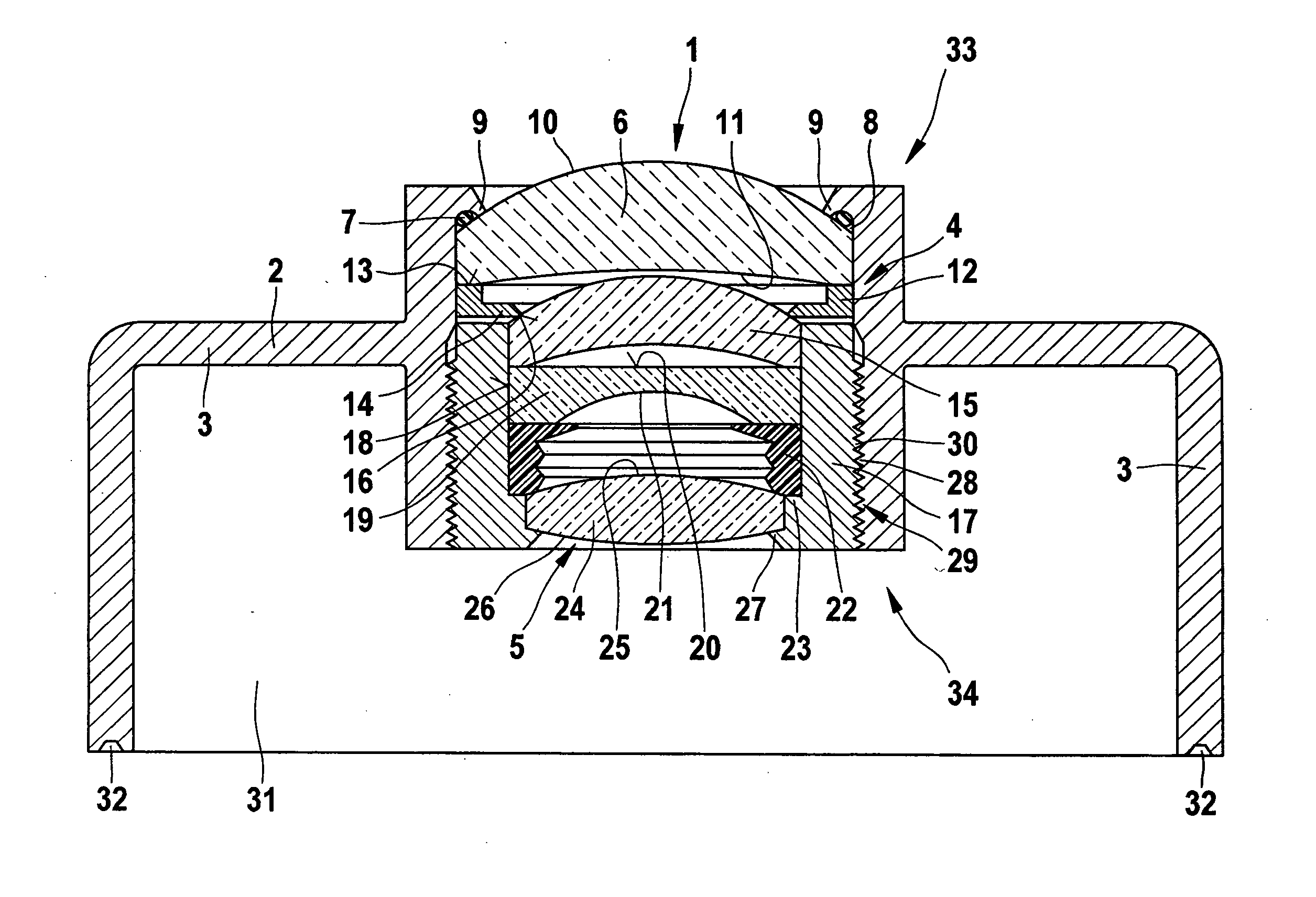
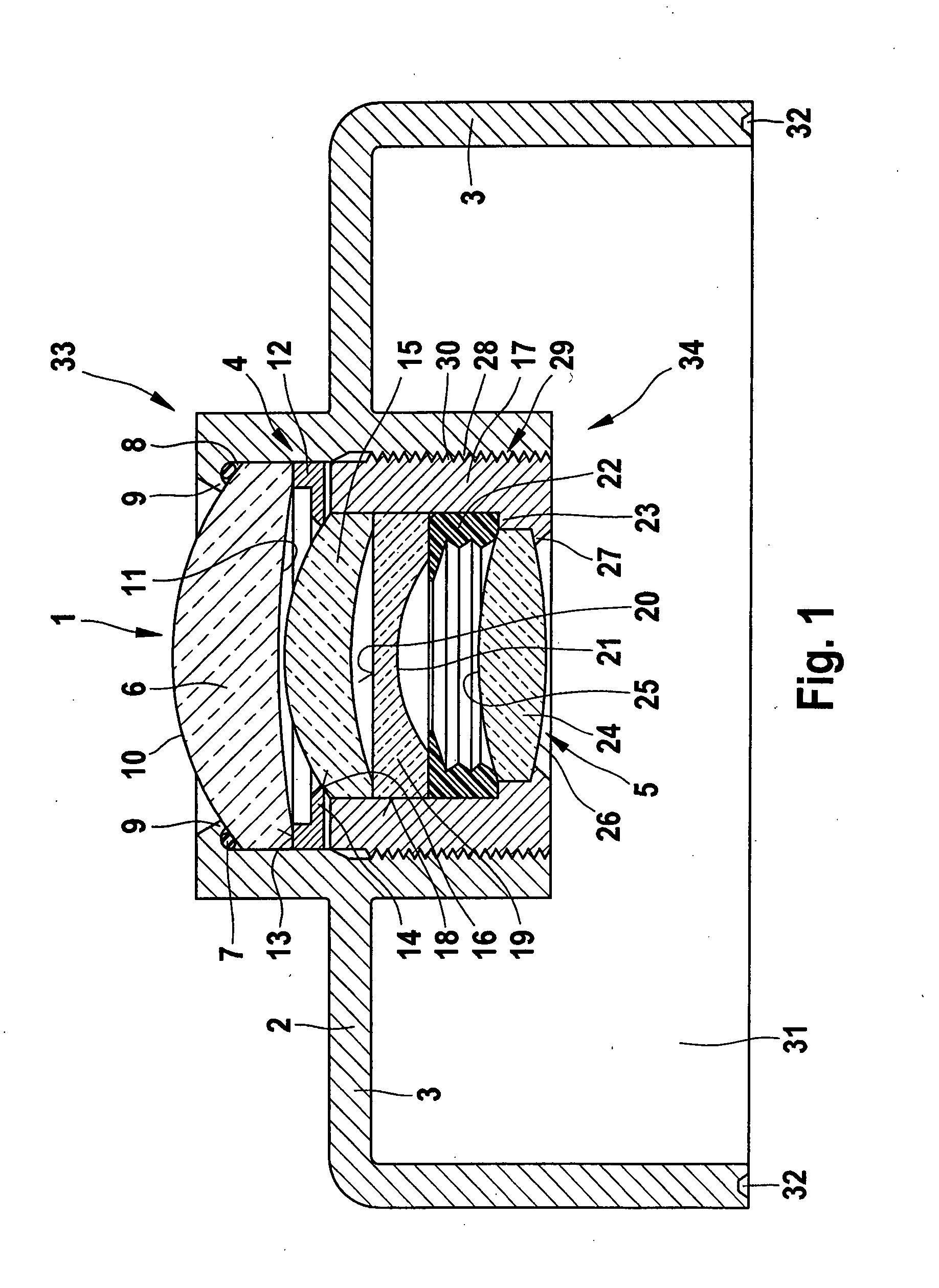
[0015]A front housing shell 3 of a camera suitable for use in motor vehicles is shown in the illustration according to FIG. 1. Front housing shell 3 of a housing 2 includes an objective lens mount 4 to accommodate a lens stack 5 that encompasses a plurality of lenses. Lens stack 5 forms an objective lens 1 of the camera suitable for use in motor vehicles.

[0016]Lens stack 5 includes an outer lens 6, which is sealed from front housing shell 3 with the aid of a sealing ring 7. To this end, front housing shell 3 has a recess 8 for sealing ring 7. Recess 8 for sealing ring 7 is formed in front housing shell 3 in such a way that gripping edges 9 grasp sealing ring 7, gripping edges 9 at the same time forming a bearing surface for outer lens 6. On its side pointing toward the outside, it is provided with a convex curvature 10 and, on its side pointing toward the interior of front housing shell 3, it is provided with a concave curvature 11. Outer lens 6 is resting on an annular spacer 12, w...


PUM

PropertyMeasurementUnit
lengthaaaaaaaaaa
flexibleaaaaaaaaaa
mechanical stressesaaaaaaaaaa

Abstract

The invention relates to a method for producing a lens system mount (4) for a lens system (1) of a camera, which can be used for vehicle applications, comprising the following method steps: The lens system mount (4) and a front housing shell (5) of the camera are produced as a single component in one working operation. The lens system mount (4) and the front housing shell (3) are made from metallic materials or plastic material with glass-fiber contents. The system mount (4) manufactured as a single piece with the front housing shell (3) is adapted to the length of the lens system (1) by machining.

Description

BACKGROUND OF THE INVENTION[0001]1. Field of the Invention[0002]The present invention relates to a camera module for use in motor vehicles.[0003]2. Description of Related Art[0004]Camera modules used in motor vehicle operation are not only subject to high mechanical stresses, but to considerable temperature fluctuations as well, and to the effects of moisture. When a camera module is used that does not have a completely impervious design, under the climatic conditions typical of automotive applications, this can lead to dew formation in the optical path on the one hand, and to degradation of the image quality on the other hand. Moisture condensation is often observed when high relative air humidity has set in in the interior of the camera module for a length of time at elevated temperatures, and the camera module is then cooled within a very short period of time.[0005]Optical recording units constructed from an objective lens and a sensor chip are typically designed to be hermetical...

Claims


Application Information

Patent Timeline
Patent Type & Authority Applications(United States)
IPC IPC(8): G03B17/00B23P17/00B23P11/00
CPCG02B7/007G02B7/021G02B7/026Y10T29/49982Y10T29/49963Y10T29/49995Y10T29/49826
Inventor GOTTWALD, FRANKAPEL, UWE
Owner ROBERT BOSCH GMBH
Why Eureka
Try Eureka