Data center optical network

a data center and optical network technology, applied in the field of high-speed optical networks, to achieve the effect of reducing cost and complexity

Inactive Publication Date: 2011-04-28
TREX ENTERPRISES CORP
View PDF8 Cites 15 Cited by
  • Summary
  • Abstract
  • Description
  • Claims
  • Application Information

AI Technical Summary

Benefits of technology

[0006]The current invention provides a new networking architecture for data centers, storage networks, and parallel computer centers. This invention eliminates the need for the large complicated core. In essence we replace the large complicated M×M switches at the core of the data center network with simple 1×N (where N is the total number of servers in the data center) switch, one at every server. Physically, we take advantage of the fact that a single optical fiber can carry thousands of high-bandwidth communications channels to enable the construction of 1×N switches that are roughly equivalent in cost and complexity to a single optical transponder unit.

Problems solved by technology

Commonly, data center servers are networked by means of complicated hardware dedicated to switching.

Method used


Image

  • Data center optical network
  • Data center optical network
  • Data center optical network

Examples


Embodiment Construction

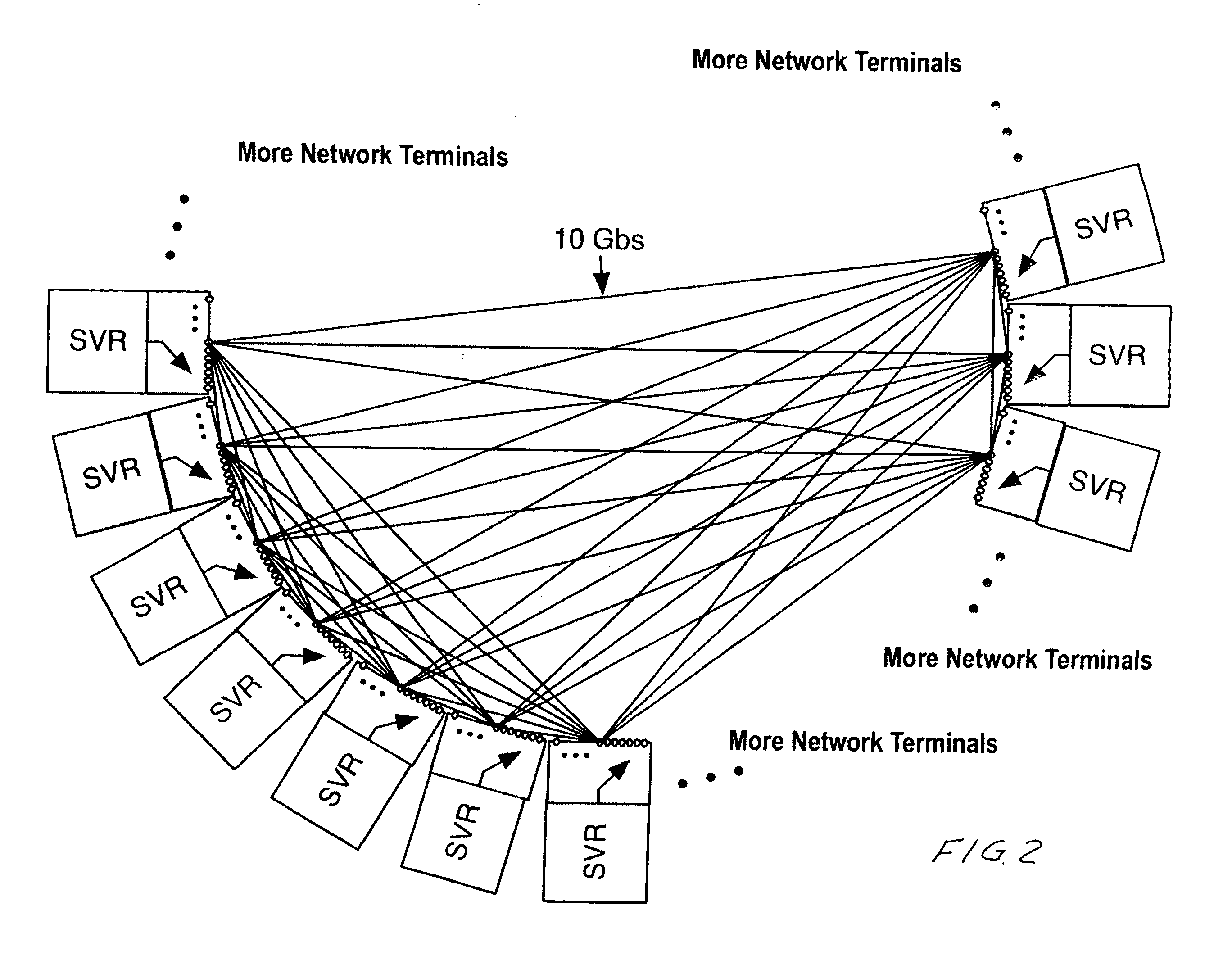
[0013]FIG. 2 shows a schematic of how the servers are linked logically. Physically, we take advantage of the fact that a single optical fiber can carry thousands of high-bandwidth communications channels to enable the construction of a communication network based on the use of 1×N switches and modulators and de-modulators associated with each 1×N switch to provide communication among hundreds or thousands of servers. Networks could include any number or servers such as: 101 servers, 1,001 servers, 10,001 servers or more. Each server is connected to all other servers by a 1×N switch. Preferred embodiments use the C and L band commonly used in telecommunications networks for long-haul transport. These two bands range in wavelength from 1530 nm to 1625 nm. Using only this region of the spectrum and efficient coherent modulation and demodulation techniques a single fiber can carry 3,300 10 Gbs channels, or enough information to link 6,600 computers together. So a system using a fiber pl...


PUM


Abstract

A new networking architecture for data centers, storage networks, and parallel computer centers. This invention eliminates the need for the large complicated core. In essence we replace the large complicated M×M switches at the core of the data center network with simple 1×N (where N is the total number of servers in the data center) switch at every server. Physically, we take advantage of the fact that a single optical fiber can carry thousands of high-bandwidth communications channels to enable the construction of 1×N switches that are roughly equivalent in cost and complexity to a single optical transponder unit.

Description

CROSS REFERENCE TO RELATED APPLICATIONS[0001]The present invention is a continuation in part of U.S. patent application Ser. No. 12 / 653,723 filed Dec. 17, 2009, and this application claims the benefit of Provisional Patent Application Ser. No. 61 / 278,425.FERERALLY SPONSORED RESEARCH[0002]The present invention was conceived in the course of performance of Contract Number NRO 000-09C-0133 with the United States Department of Defense and the United States Government has rights in the invention.FIELD OF THE INVENTION[0003]The present invention relates to high speed optical networks and in particular to high speed optical networks for data centers.BACKGROUND OF THE INVENTION[0004]Current data centers provide networking between individual hosts or servers in the data center using large and complicated Ethernet, Fiber-Chanel or other similar switches. FIG. 1 shows the architecture commonly used in these facilities. These data centers typically comprise a storage area network, referred to a...

Claims


Application Information

Patent Timeline
Patent Type & Authority Applications(United States)
IPC IPC(8): H04J14/02
CPCH04Q11/0005H04J14/021
Inventor BARRETT, TODD
Owner TREX ENTERPRISES CORP
Why Eureka
Try Eureka