Method and apparatus for treating renal disease with hemodialysis utilizing pulsatile pump

a technology of pulsatile pump and hemodialysis, which is applied in the field of treatment of end-stage renal disease (esrd) with hemodialysis, can solve the problems of blood/dialysate mismatch, reducing the exchange efficiency, and reducing the efficiency of exchange, so as to increase the transmembrane pressure, reduce the dead region, and increase the efficiency of transport

Inactive Publication Date: 2011-04-28
EAST CAROLINA UNIVERISTY
View PDF15 Cites 39 Cited by
  • Summary
  • Abstract
  • Description
  • Claims
  • Application Information

AI Technical Summary

Benefits of technology

[0008]It has been discovered that the use of pulsatile flow in the blood or dialysate circuits during hemodialysis can provide a number of advantages. These include increased efficiency of transport, reduction in dead regions, and intermittent increased transmembrane pressure.

Problems solved by technology

In each of these regions the component exchange between the blood and the dialysate can be adversely affected, as fluid in the dead regions and the regions of laminar flow tends to have less surface area contact with the membrane, thereby reducing the efficiency of exchange.
Also, the constant flow of dialysate can create “shunting” of dialysate in certain regions, which can lead to blood / dialysate mismatch.

Method used


Image

  • Method and apparatus for treating renal disease with hemodialysis utilizing pulsatile pump
  • Method and apparatus for treating renal disease with hemodialysis utilizing pulsatile pump
  • Method and apparatus for treating renal disease with hemodialysis utilizing pulsatile pump

Examples


example 1

In Vitro Analysis of Pulsatile Flow of Dialysate

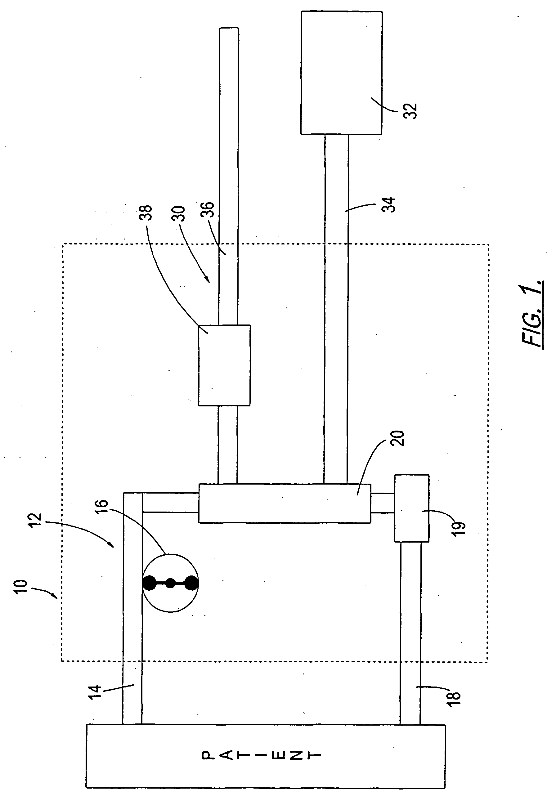
[0029]In vitro dialysis experiments were conducted using a pair of pools filled with liquid and performing dialysis on these liquids. Experimental blood and dialysate circuits were created that each included a two-liter reservoir connected to a roller head pump (Sarns 7400 MDX, available from Sarns, Inc., Ann Arbor, Mich.). The roller head pump was connected to a dialysis filter, which was in turn connected to the two liter reservoir to form a closed loop. All connections were made with ⅜ inch plastic tubing.

[0030]For the control apparatus, the dialysis machine used was a Fresenius 2008H dialysis machine (available from Fresenius USA, Lexington, Mass.), which employs a relatively constant flow pump. The experimental system employed a Fresenius F7NR dialysis filter (available from Fresenius USA, Lexington, Mass.) and a Sarns roller head pump that operated at 50 cycles per minute and at a pulse pressure of 80 mm Hg.

[0031]For each system,...

example 2

[0034]The experimental apparatus used in Example 1 was employed again to perform dialysis on a dog with the following changes. A HB 500 filter was employed with the Century System III dialysis machine (both available from Gambro Corp., Lakewood, Colo.). Also, rather than tap water, a standard 3K dialysate was used to hemodialyze the dog. Pulsatile flow was induced in the blood subsystem with a roller head pump operating at 50 cycles / minute. In addition, both blood urea nitrogen (BUN) and creatinine levels were measured (BUN was measured with a Olympus AU640 instrument and creatinine was measured by a Jaffe assay).

[0035]The results of the procedure are shown in Tables 3 and 4 and FIGS. 4 and 5.

TABLE 3BUN LevelProcedureBaseline60 min120 minPost 30 minControl Dialysis110110 (0.0%)80 (27.3%)97Variable Speed Dialysis126 84 (33.3%)69 (45.3%)73% Greater Efficiency39.8%

TABLE 4Creatinine LevelProcedureBaseline60 min120 minPost 30 minControl Dialysis10.28.7 (14.7%)7.3 (28.5%)9.1Variable Speed...


PUM


Abstract

A method of removing toxins from blood from a patient in need of such toxin removal includes: providing a countercurrent dialysis filter (20) having a blood compartment and a dialysate compartment separated from the blood compartment by a semi-permeable membrane; conveying blood from the patient through the blood compartment of a countercurrent filter (20) an back to the patient; and drawing dialysate from a reservoir (32) through the dialysate compartment of the countercurrent filter (20). At least one of the blood or dialysate experiences pulsatile flow. The steps are carried out such that blood toxins are drawn from the blood compartment through the semi-permeable membrane into the dialysate compartment.

Description

FIELD OF THE INVENTION[0001]The present invention is directed generally to treatment of renal disease, and more specifically to treatment of end stage renal disease (ESRD) with hemodialysis.BACKGROUND OF THE INVENTION[0002]Hemodialysis is a well-known treatment technique for ESRD, a condition in which the patient's renal system has essentially ceased to remove waste products and contaminants from the blood. Hemodialysis is a process that involves removing blood from the vasculature of a patient (usually a shunt or vein), purifying it with dialysate (a fluid that helps to remove toxins and return electrolytes to the blood), and returning the blood to the patient (usually through another vein).[0003]Hemodialysis machines typically operate with separate compartments for blood and dialysate. In conventional systems, the compartments are separated by a semi-permeable membrane that allows selective diffusion; toxins are removed from the blood, and electrolytes are added to bring the elect...

Claims


Application Information

Patent Timeline
Patent Type & Authority Applications(United States)
IPC IPC(8): A61M1/16A61M1/10B01D65/08
CPCA61M1/16A61M2205/75A61M1/1649B01D2321/2066A61M1/1005B01D65/08A61M2202/0498A61M2205/15A61M60/562A61M60/113A61M60/279A61M60/37
Inventor MCCOTTER, CRAIGBOLIN, PAUL
Owner EAST CAROLINA UNIVERISTY
Why Eureka
Try Eureka