Heat dissipating cavity

a heat dissipating cavity and cavity technology, applied in lighting and heating apparatus, semiconductor devices, semiconductor/solid-state device details, etc., can solve the problems of increasing the temperature, the temperature of electronic parts exceeding the tolerance limit, and the material used usually has low thermal conductivity coefficient, so as to achieve the effect of efficient dissipation of hea

Inactive Publication Date: 2011-05-05
BEIJING AVC TECH RES CENT
View PDF19 Cites 9 Cited by
  • Summary
  • Abstract
  • Description
  • Claims
  • Application Information

AI Technical Summary

Benefits of technology

[0011]It is an object of this present invention to provide a he

Problems solved by technology

But due to the limitation of existing casting technology, the material used usually has low thermal conductivity coefficient.
The heat generated by electronic parts tends to concentrate in one local area, thereby greatly raising the temperature of that local area and causing the temperature of those electronic parts to exceed their tolerance limit.
This results in uneven temperature distribution in the cavity and the exterior fins, and seriously compromises the heat dissipating efficiency of the cavity.
But this kind of solution itself leads to other technical problems, such as the overweight of the cavity.
Owing to the limitation of existing manufacturing technology, the material of known cavities has low thermal conductivity coefficient, causing a large amount of heat to concentrate in the small local

Method used


Image

  • Heat dissipating cavity
  • Heat dissipating cavity
  • Heat dissipating cavity

Examples


Embodiment Construction

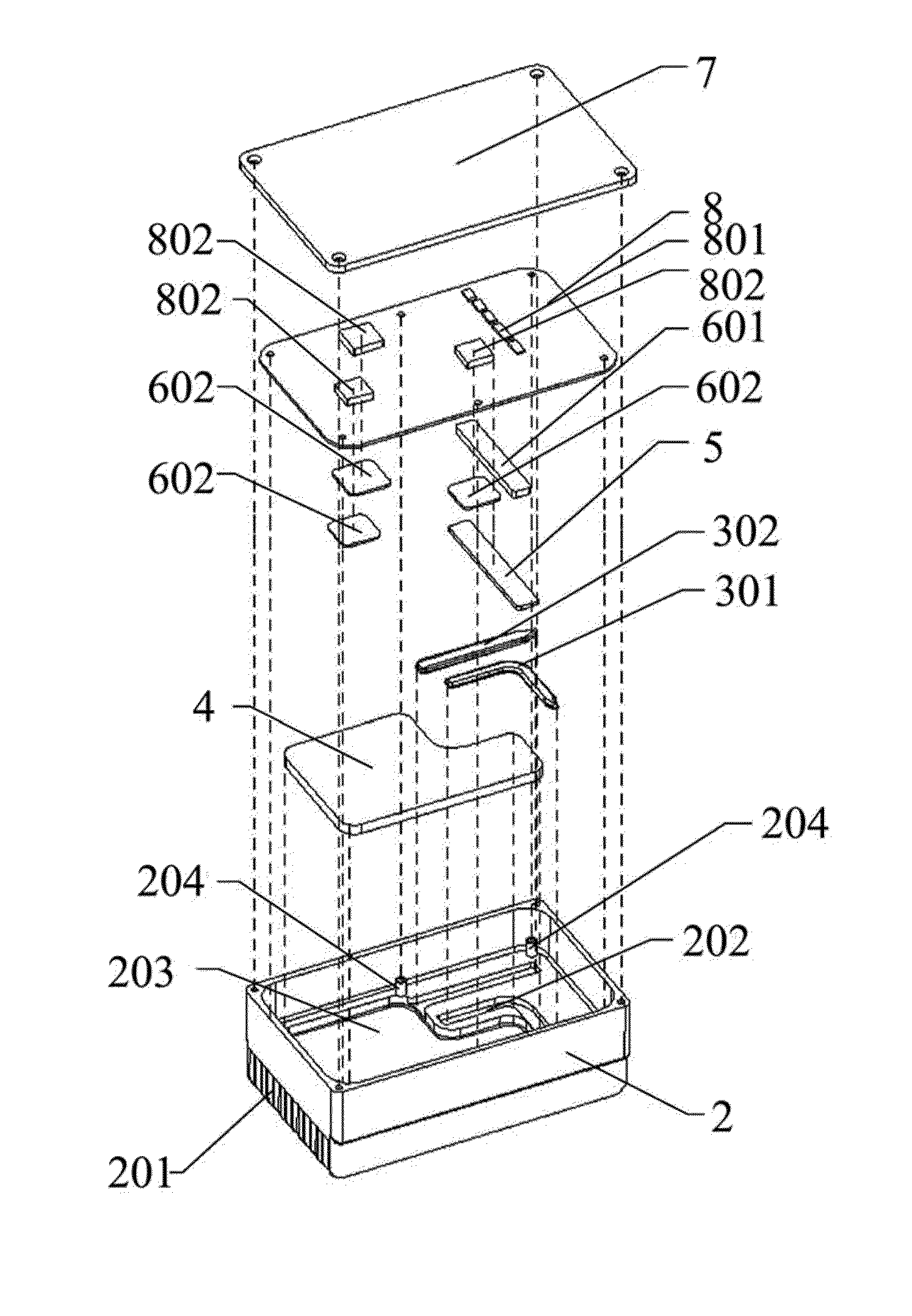
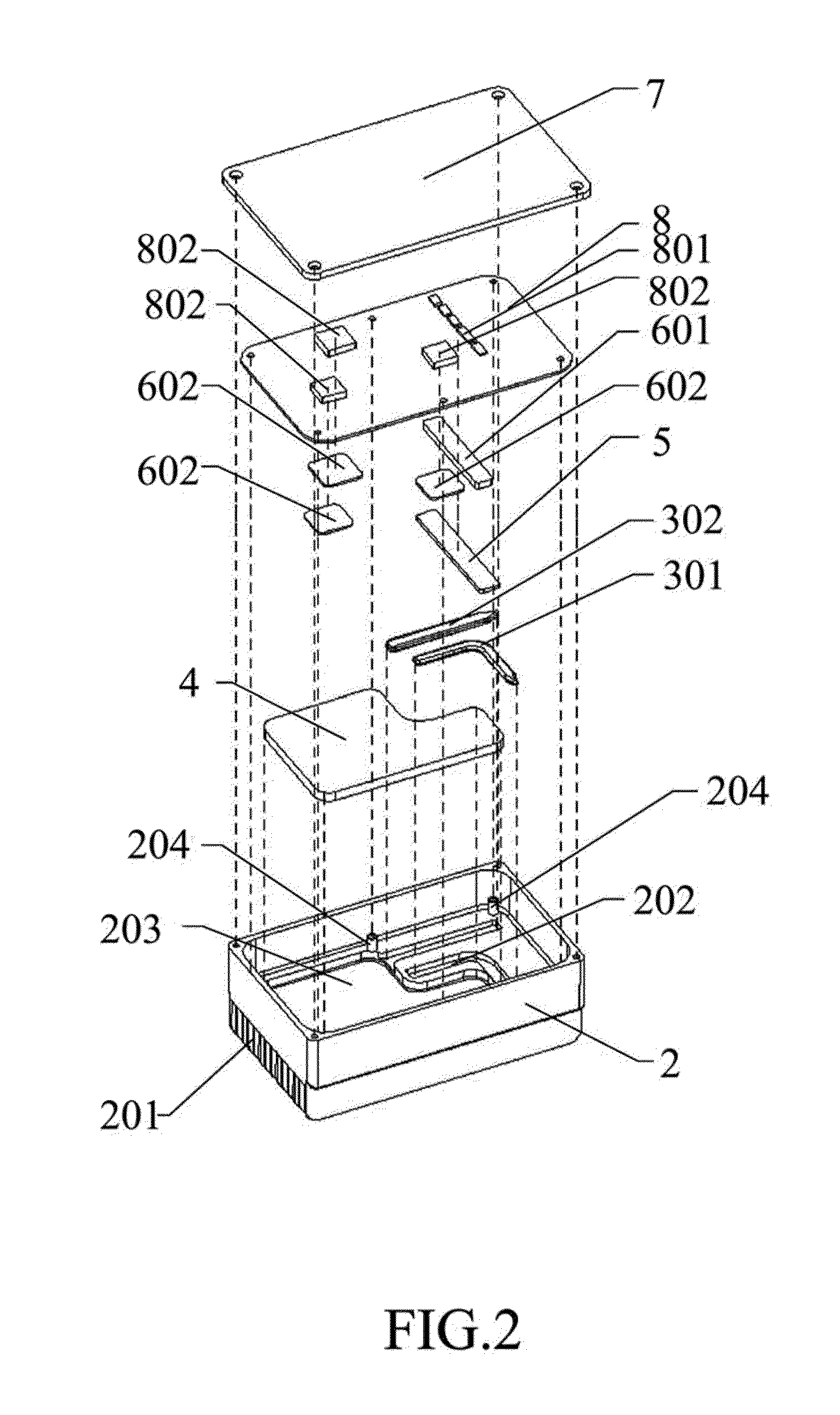
[0021]Several aspects of the invention are hereinafter described in detail with reference to FIGS. 2 to 4.

[0022]Referring to FIG. 2, the present invention is a heat dissipating cavity. The preferred embodiment includes a cavity 2, temperature equalizing elements (an L-shape heat pipe 301, a straight heat pipe 302, and a heat expansion plate 4 are employed in the preferred embodiment), a copper plate 5, high thermal conductive pads 601 and 602, and a cover 7. On the outside of the cavity is disposed a plurality of heat dissipating fins 201. On the inner base of the cavity 2 are disposed a heat pipe groove 202 and a heat expansion plate groove 203. The cavity 2 of the present invention is designed for the electronic board 8, whereon are disposed heating elements 801 and 802.

[0023]In the preferred embodiment of the invention, the L-shape heat pipe 301 and the straight heat pipe 302 can be adhered to the copper plate 5 by welding, heat conductive glue, or screws before being disposed in...


PUM


Abstract

A heat dissipating cavity includes a cavity made of high thermal conductive material having a plurality of heat dissipating fins on the outside thereof, and temperature equalizing elements including heat pipes and heat expansion plates, which can be used individually or collectively. The heat generated by the heating electronic elements inside the cavity is first effectively conducted to the temperature equalizing elements, wherefrom effectively and evenly conducted to the entire cavity, and finally released out of the system by the plurality of heat dissipating fins. The use of temperature equalizing elements increases the homogeneity of the cavity's overall temperature and greatly improves the efficiency of heat dissipation.

Description

BACKGROUND OF THE INVENTION[0001]1. Field of the Invention[0002]The present invention relates to an electronic heat dissipating apparatus and particularly to an electronic heat dissipating apparatus which employs temperature equalizing elements.[0003]2. Brief Description of Related Art:[0004]Existing cavities are mostly made of metal and manufactured by casting. But due to the limitation of existing casting technology, the material used usually has low thermal conductivity coefficient. The heat generated by electronic parts tends to concentrate in one local area, thereby greatly raising the temperature of that local area and causing the temperature of those electronic parts to exceed their tolerance limit. Yet the remaining big area in the cavity, which is away from those heating electronic parts, is far lower in temperature than the said local area. This results in uneven temperature distribution in the cavity and the exterior fins, and seriously compromises the heat dissipating ef...

Claims


Application Information

Patent Timeline
IPC IPC(8): H01L23/367F28D15/04F28F7/00H01L23/427
CPCF28D15/0266H01L23/36H01L23/427H01L2924/0002H01L2924/00
Inventor LI, JIWANG, DA-MING
Owner BEIJING AVC TECH RES CENT
Why Eureka
Try Eureka