Method for manufacturing molded foam

Active Publication Date: 2011-05-05
KYORAKU CO LTD
6 Cites 10 Cited by

AI-Extracted Technical Summary

Problems solved by technology

As a result, a strength (such as impact resistance) of the molded foam becomes insufficient.
Further, according to the method for manufacturing a molde...

Method used

[0053]Further, since a method in which the ring-shaped piston 12 in the die external cylinder 18 extrudes the resin blend is employed (accumulator head system or accumulator-inside-die system), it is possible to reduce a length between a top and a bottom of the die outlet 11, and thus to increase an extrusion speed. Therefore, it is possible to maintain a condition of the foamed cells.
[0054]Here, it is preferable that the speed of extruding the resin blend be not less than 700 kg/hour. In this case, it is possible to obtain a molded foam with higher surface smoothness.
[0057]Further, among these, propylene homopolymer having a long chain branching structure is particularly preferable. Since using the propylene homopolymer increases a melt tension of the resin, the resin foams more easily and the foamed cells are further uniformized.
[0062]The resin blend is preferably further added with styrene elastomer and/or low-density polyethylene. Addition of styrene elastomer or low-density polyethylene further improves an impact intensity of the molded foam at a low temperature.
[0071]Further, in the foaming method, it is preferable to use the supercritical fluid. In particular, it is preferable that the resin blend be caused to foam using the carbonic acid gas or the nitrogen gas in a supercritical state. In this case, it is possible to realize uniform and reliable foaming. Here, a nitrogen supercritical fluid can be obtained by setting a critical temperature of nitrogen to be not less than −149.1° C. and its critical pressure to be not less than 3.4 MPa, and a carbon dioxide supercritical fluid can be obtained by setting a critical temperature of carbon dioxide to be not less than 31° C. and its critical pressure to be not less than 7.4 MPa.
[0078]According to the method for manufacturing a molded foam, the protuberances 13a of the split mold blocks 13 serve to form recesses in a surface of the molded foam, as well as to closely attach the facing portions of the inner wall surface of the molded foam to each other. Therefore, it is possible to manufacture the molded foam in which the recesses are formed in its surface with a simple configuration.
[0079]Further, according to this manufacturing method, it is possible to reduce a manufacturing cost since the attaching step S2 and the mold clamping step S3 are performed at the same time.
[0080]A core 15 provided at a tip end of the die 10 used in this manufacturing method is provided with a suction inlet 15a (see FIG. 3). In the attaching step, air between the facing portions of the inner wall surface of the cylinder-shaped foamed parison 20, that is, the air in the cylinder-shaped foamed parison, is sucked through the suction inlet 15a. Thus, it is possible to further improve the close attachment between the facing portions of the inner wall surface of the cylinder-shaped foamed parison 20.
[0082]According to the method for manufacturing a molded foam of the first embodiment, the foamed parison laminated body 30 is formed by performing the attaching step S2 in which the facing portions of the inner wall surface of the cylinder-shaped foamed parison 20 are closely attached to each other without fail. Thus, it is possible to suppress generation of a hollow part. Consequently, the molded foam obtained by the method for manufacturing a molded foam is reduced in weight and is excellent in strength (impact resistance and the like).
[0089]As illustrated in FIG. 6A, recesses are formed in a surface of the molded foam 40, and this realizes weight reduction. Further, as illustrated in FIG. 6B, the molded foam 40 is filled with the thermoplastic resin, so that no hollow part is formed. Consequently, the molded foam 40 is lightweight and excellent in strength.
[0090]The molded foam 40 has a closed cell structure including a plurality of foamed cells. Here, the closed cell structure refers to a structure including a plurality of foamed cells where a proportion of closed cells is not less than 50%. Consequently, excellent surface smoothness can be provided.
[0095]In particular, it is possible to reduce the weight of an automobile by using the molded foam 40 as automotive structural members for cargo floor boards, deck boards, rear parcel shelves, roof panels, interior panels such as door trims, door inner panels, platforms, hardtops, sun roofs, hoods, bumpers, floor spacers, and tibia pads, so that fuel efficiency can be improved.
[0105]Therefore, according to the method for manufacturing a molded foam, it is possible to prevent the molded foam from being partially thin, and thus it is possible to suppress the generation of the hollow part.
[0123]As illustrated in FIG. 12, in the attaching step S7, the facing portions of the inner wall surface of the cylinder-shaped foamed parison 20 are sandwiched and closely attached to each other by a pair of rollers 24 immediately after the cylinder-shaped foamed parison 20 is extruded. Thus, the foamed parison laminated body 30 is formed. In this case, it is possible to facilitate the close attachment between the facing portions of the inner wall surface of the cylinder-shaped foamed parison 20 over a wide area.
[0154]As illustrated in FIG. 17, in the attaching step S10, a cylinder-shaped foamed parison 120 is sandwiched by a pair of pressure-attachment rollers 124 immediately after the cylinder-shaped foamed parison 120 is extruded. Thus, a foamed parison laminated body 130 is formed by closely attaching facing portions of an inner wall surface 120a of the cylinder-shaped foamed parison 120 to each other. Consequently, it is possible to closely attach the facing portions of the inner wall surface 120a of the cylinder-shaped foamed parison 120 to each other continuously over a wide area. Consequently, it is possible to make a thickness of the foamed parison laminated body 130 even. In addition, as this is realized by only using the pair of pressure-attachment rollers, a device can be simplified.
[0155]Here, it is preferable that a pressure of sandwiching of the pressure-attachment rollers 124 be not more than 1 kg/cm2. In this case, the moldability is improved since cells that are formed due to the foaming are not easily broken even when the cylinder-shaped foamed parison 120 is sandwiched by the pressure-attachment rollers 124.
[0156]According to the method for manufacturing a molded foam of the seventh embodiment, the suction inlet 115a is provided for a core at a tip end of a die 110. In the attaching step S10, the air between the facing portions of the inner wall surface 120a of the cylinder-shaped foamed parison 120, that is, the air in the cylinder-shaped foamed parison 120 is sucked through the suction inlet 115a. Thus, it is possible to suppress the generation of the hollow part, which can result in reduction of the strength, without breaking the cells. Moreover, it is possible to further improve the close attachment between the facing portions of the inner wall surface 120a of the cylinder-shaped foamed parison 120.
[0158]By blowing the air through the air inlets 121 to the outer wall surface 120b of the foamed parison laminated body 130, i...

Benefits of technology

[0015]The present invention is made in view of the circumstances described above, and an object thereof...

Abstract

An object of the invention is to provide a method for manufacturing a molded foam which is lightweight and excellent in strength. According to the invention, a method for manufacturing a molded foam from a foamed parison includes: an extruding step of extruding a resin blend containing a foaming agent and a thermoplastic resin to form a foamed parison; an attaching step of closely attaching facing portions of an inner wall surface of the foamed parison to each other to form a foamed parison laminated body; a mold clamping step of sealing and mold clamping the foamed parison laminated body by clamping the foamed parison laminated body by split mold blocks; and a sucking step of sucking air between the split mold blocks to reduce a pressure between the split mold blocks, after the attaching step and the mold clamping step.

Application Domain

Semi-permeable membranesHollow wall articles +1

Technology Topic

Composite materialShell molding +1

Image

  • Method for manufacturing molded foam
  • Method for manufacturing molded foam
  • Method for manufacturing molded foam

Examples

  • Experimental program(9)

Example

First Embodiment
[0042]The following describes a first embodiment of a method for manufacturing a molded foam according to the present invention, taking an example in which a cylinder-shaped foamed parison is used.
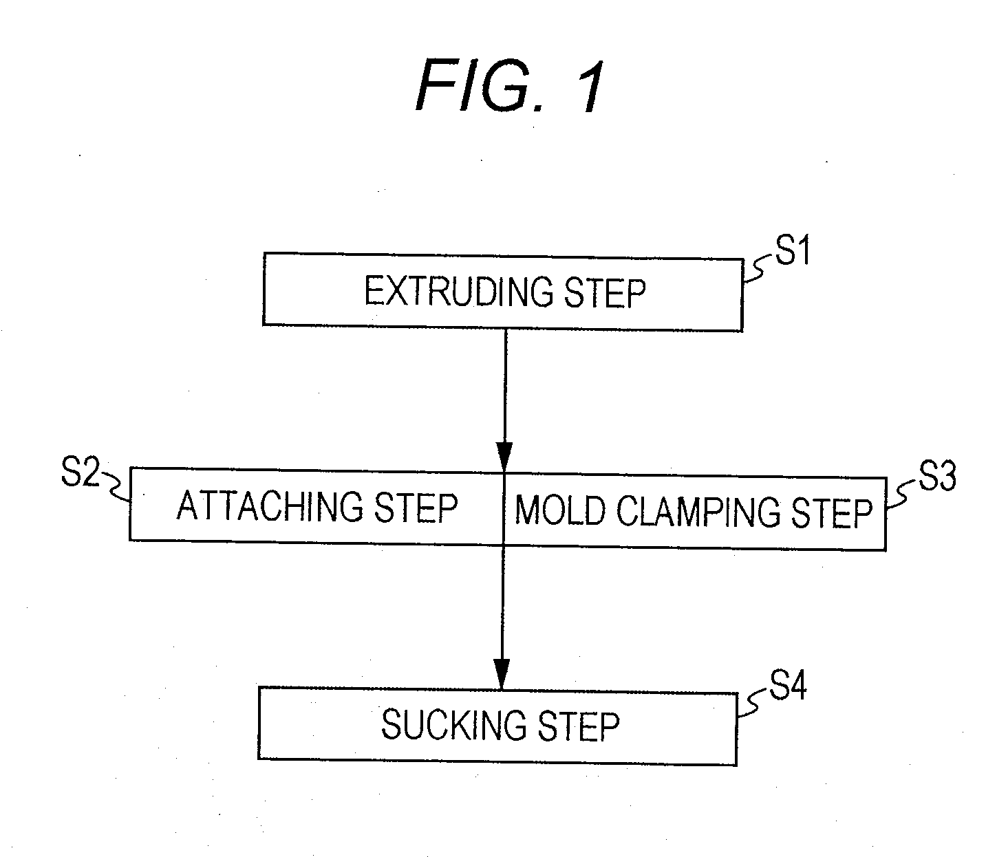
[0043]FIG. 1 is a flowchart of the method for manufacturing a molded foam according to the first embodiment.
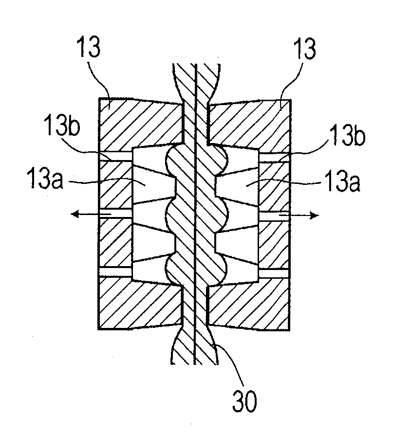
[0044]Referring to FIG. 1, the method for manufacturing a molded foam according to the first embodiment includes an extruding step S1, an attaching step S2, a mold clamping step S3, and a sucking step S4. In the extruding step S1, a cylinder-shaped foamed parison in a cylinder shape is formed by extruding a resin blend containing a foaming agent and a thermoplastic resin. In the attaching step S2, facing portions of an inner wall surface of the cylinder-shaped foamed parison are closely attached to each other, so that a foamed parison laminated body is formed. In the mold clamping step S3, sealing and mold clamping are performed to the foamed parison laminated body by clamping the foamed parison laminated body by split mold blocks. In the sucking step S4, air between the split mold blocks is sucked to reduce a pressure between the split mold blocks. As will be described later, in the method for manufacturing a molded foam according to the first embodiment, the attaching step S2 and the mold clamping step S3 are performed at the same time. Specifically, the extruding step S1, the attaching step S2 and the mold clamping step S3 (simultaneous), and the sucking step S4 are performed in the stated order.
[0045]According to the method for manufacturing a molded foam described above, it is possible to manufacture a molded foam which is lightweight and excellent in strength (including no hollow part).
[0046]In the following, each of the steps will be described in further detail.
(Extruding Step)
[0047]The extruding step S1 is a step in which the cylinder-shaped foamed parison in the cylinder shape is formed by extruding the resin blend containing the foaming agent and the thermoplastic resin through an extrusion outlet.
[0048]FIG. 2 is a partial sectional view illustrating a die used in the method for manufacturing a molded foam according to the first embodiment. FIG. 3 is a vertical sectional view illustrating a state in which the cylinder-shaped foamed parison is extruded between the split mold blocks in the method for manufacturing a molded foam according to the first embodiment.
[0049]Referring to FIG. 2, a die 10 includes a die external cylinder 18, a mandrel 17 disposed at the substantial center of the die external cylinder 18, a cylinder-shaped space 19 between the die external cylinder 18 and the mandrel 17, a ring-shaped piston 12 for pressing the resin blend retained in the cylinder-shaped space 19 downward, and the extrusion outlet (die outlet 11) that discharges the resin blend.
[0050]In the extruding step S1, first, the resin blend as a supercritical fluid in which the thermoplastic resin and the foaming agent are blended is kneaded in the die 10. Then, the kneaded resin blend is retained in the cylinder-shaped space 19 between the mandrel 17 and the die external cylinder 18. Here, it is preferable that an amount of the retained resin blend be 5 to 40 liters.
[0051]Subsequently, after a predetermined amount of resin blend is retained in the cylinder-shaped space 19, the ring-shaped piston 12 is pressed downward. Thus, the resin blend is extruded in a cylindrical shape between split mold blocks 13 through the die outlet 11 as illustrated in FIG. 3. The resin blend foams at the same time upon extrusion to form a cylinder-shaped foamed parison 20.
[0052]In the method for manufacturing a molded foam described above, the resin blend is retained in the cylinder-shaped space 19. Therefore, sizes of foamed cells are uniformized while the resin blend is retained.
[0053]Further, since a method in which the ring-shaped piston 12 in the die external cylinder 18 extrudes the resin blend is employed (accumulator head system or accumulator-inside-die system), it is possible to reduce a length between a top and a bottom of the die outlet 11, and thus to increase an extrusion speed. Therefore, it is possible to maintain a condition of the foamed cells.
[0054]Here, it is preferable that the speed of extruding the resin blend be not less than 700 kg/hour. In this case, it is possible to obtain a molded foam with higher surface smoothness.
[0055]Examples of the thermoplastic resin include polyolefin-based resins such as a polyethylene resin and a polypropylene resin.
[0056]Among these, it is preferable that the thermoplastic resin include a propylene unit. Specific examples include propylene homopolymer, ethylene-propylene block copolymer, ethylene-propylene random copolymer, and the like.
[0057]Further, among these, propylene homopolymer having a long chain branching structure is particularly preferable. Since using the propylene homopolymer increases a melt tension of the resin, the resin foams more easily and the foamed cells are further uniformized.
[0058]It is preferable that the propylene homopolymer having a long chain branching structure be propylene homopolymer having a weight average ramification index of not more than 0.9. Further, a weight average ramification index g′ is represented by V1/V2. V1 indicates an intrinsic viscosity number of branched polyolefin, and V2 indicates an intrinsic viscosity number of linear polyolefin having the same weight average molecular weight as that of branched polyolefin.
[0059]As the thermoplastic resin, it is preferable to use a polypropylene resin having a melt tension in a range from 30 to 350 mN at 230° C. Since a polypropylene-based foaming resin shows strain hardening when the melt tension is within the above range, it is possible to obtain a high expansion ratio.
[0060]It is preferable that a melt flow rate (MFR) of the thermoplastic resin at 230° C. be 1 to 10. Here, the MFR is a value measured according to JIS K-7210.
[0061]When the MFR is less than 1, it tends to be difficult to increase the extrusion speed as compared to the case in which the MFR is within the above range. When the MFR exceeds 10, it tends to be difficult to perform blow molding due to an occurrence of drawdown and the like as compared to the case in which the MFR is within the above range.
[0062]The resin blend is preferably further added with styrene elastomer and/or low-density polyethylene. Addition of styrene elastomer or low-density polyethylene further improves an impact intensity of the molded foam at a low temperature.
[0063]Although not particularly limited, styrene elastomer is preferably elastomer having a styrene unit with hydrogenated molecules. Specific examples include hydrogenated elastomer such as styrene-ethylene/butylene-styrene block copolymer, styrene-ethylene/propylene-styrene block copolymer, and styrene-butadiene random copolymer.
[0064]It is preferable that a compounding ratio of styrene elastomer be within a range of less than 40 wt % of the thermoplastic resin in perspective of moldability.
[0065]Further, it is preferable that an amount of styrene contained in styrene elastomer be less than 30 wt % in perspective of the impact intensity at a low temperature, and more preferably, less than 20 wt %.
[0066]It is preferable that low-density polyethylene that is used has a density of not more than 0.91 g/cm3 in perspective of the impact intensity at a low temperature. In particular, it is preferable to use straight-chain ultralow density polyethylene polymerized by a metallocene-based catalyst.
[0067]It is preferable that a compounding ratio of low-density polyethylene be within a range of less than 40 wt % of the thermoplastic resin in perspective of the rigidity and a heat resistance.
[0068]The resin blend described above can be added with a nucleating agent, a coloring agent or the like, in addition to styrene elastomer, low-density polyethylene, and foaming agent.
[0069]Specific examples of the foaming agent include an inorganic foaming agent such as air, a carbonic acid gas, a nitrogen gas, and water, or an organic foaming agent such as butane, pentane, hexane, dichloromethane, and dichloroethane.
[0070]Among these, it is preferable to use the air, the carbonic acid gas or the nitrogen gas as the foaming agent. Since no organic substance is added when using any of these, durability and the like do not decrease.
[0071]Further, in the foaming method, it is preferable to use the supercritical fluid. In particular, it is preferable that the resin blend be caused to foam using the carbonic acid gas or the nitrogen gas in a supercritical state. In this case, it is possible to realize uniform and reliable foaming. Here, a nitrogen supercritical fluid can be obtained by setting a critical temperature of nitrogen to be not less than −149.1° C. and its critical pressure to be not less than 3.4 MPa, and a carbon dioxide supercritical fluid can be obtained by setting a critical temperature of carbon dioxide to be not less than 31° C. and its critical pressure to be not less than 7.4 MPa.
(Attaching Step and Mold Clamping Step)
[0072]The attaching step S2 is a step in which the facing portions of the inner wall surface of the cylinder-shaped foamed parison are closely attached to each other, so that the foamed parison laminated body is formed. The mold clamping step S3 is a step in which the sealing and the mold clamping are performed to the foamed parison laminated body by clamping the foamed parison laminated body by the split mold blocks.
[0073]FIG. 4A is a sectional view taken along a line A-A in FIG. 3. FIG. 4B is a horizontal sectional view illustrating a state after the split mold blocks are closed and the attaching step and the mold clamping step are performed to the cylinder-shaped foamed parison illustrated in FIG. 4A.
[0074]Referring to FIG. 4A, in the method for manufacturing a molded foam according to the first embodiment, the split mold blocks 13 are provided with protuberances 13a for pressing the cylinder-shaped foamed parison 20 and closely attaching the facing portions of the inner wall surface to each other.
[0075]In the attaching step S2, by clamping the cylinder-shaped foamed parison 20 by the split mold blocks 13, the protuberances 13a provided for the split mold blocks 13 press an outer wall surface of the cylinder-shaped foamed parison 20. Thus, as illustrated in FIG. 4B, the facing portions of the inner wall surface of the cylinder-shaped foamed parison 20 are closely attached to each other, so that a foamed parison laminated body 30 is formed (attaching step S2). Specifically, an adhered area is formed without fail at a portion clamped by the protuberances 13a of the split mold blocks 13 in the foamed parison laminated body 30.
[0076]Further, at the same time as the attaching step, the cylinder-shaped foamed parison 20 (foamed parison laminated body 30) is clamped by the split mold blocks 13, and then sealed and mold-clamped (mold clamping step S3).
[0077]Thus, the foamed parison laminated body 30 is obtained.
[0078]According to the method for manufacturing a molded foam, the protuberances 13a of the split mold blocks 13 serve to form recesses in a surface of the molded foam, as well as to closely attach the facing portions of the inner wall surface of the molded foam to each other. Therefore, it is possible to manufacture the molded foam in which the recesses are formed in its surface with a simple configuration.
[0079]Further, according to this manufacturing method, it is possible to reduce a manufacturing cost since the attaching step S2 and the mold clamping step S3 are performed at the same time.
[0080]A core 15 provided at a tip end of the die 10 used in this manufacturing method is provided with a suction inlet 15a (see FIG. 3). In the attaching step, air between the facing portions of the inner wall surface of the cylinder-shaped foamed parison 20, that is, the air in the cylinder-shaped foamed parison, is sucked through the suction inlet 15a. Thus, it is possible to further improve the close attachment between the facing portions of the inner wall surface of the cylinder-shaped foamed parison 20.
[0081]Further, in the mold clamping step S3, air is blown into the split mold blocks 13 through air inlets 13b provided for the split mold blocks 13. This increases an atmospheric pressure within a sealed space between the split mold blocks 13. Consequently, the close attachment between the facing portions of the inner wall surface of the cylinder-shaped foamed parison 20 is improved even further. Specifically, laminated portions that are not clamped by the protuberances 13a are closely attached by an air pressure. Here, it is preferable that a pressure at which the air is blown be 0.05 to 0.15 Mpa in perspective of maintenance of the shape of the foamed cells, and it is preferable that a temperature of the air that is blown be higher than that of the foamed parison in perspective of prevention of cooling of the foamed parison.
[0082]According to the method for manufacturing a molded foam of the first embodiment, the foamed parison laminated body 30 is formed by performing the attaching step S2 in which the facing portions of the inner wall surface of the cylinder-shaped foamed parison 20 are closely attached to each other without fail. Thus, it is possible to suppress generation of a hollow part. Consequently, the molded foam obtained by the method for manufacturing a molded foam is reduced in weight and is excellent in strength (impact resistance and the like).
[0083]Further, according to the method for manufacturing a molded foam, the portions of the inner wall surface that are laminated in the mold clamping step S3 are not easily separated by performing the attaching step S2. Consequently, it is possible to make the entire molded foam to have a sufficient foaming state since the expansion ratio can be increased. Thus, it is possible to further reduce the weight of the molded foam.
(Sucking Step)
[0084]The sucking step S4 is a step in which the air between the split mold blocks 13 is sucked to reduce the pressure between the split mold blocks 13 in a state in which the foamed parison laminated body 30 obtained through the attaching step S2 and the mold clamping step S3 is sealed between the split mold blocks 13.
[0085]FIG. 5A is a horizontal sectional view illustrating a state before performing the sucking step to the foamed parison laminated body in the method for manufacturing a molded foam according to the first embodiment. FIG. 5B is a horizontal sectional view illustrating a state after performing the sucking step to the foamed parison laminated body in the method for manufacturing a molded foam according to the first embodiment.
[0086]Referring to FIG. 5A, in the sucking step S4, the air between the split mold blocks 13 is sucked through the air inlets 13b provided for the split mold blocks 13. Thus, the atmospheric pressure within the sealed space between the split mold blocks 13 decreases. Consequently, as illustrated in FIG. 5B, the foamed parison laminated body 30 is expanded toward the air inlets 13b. Since cells grow along with this, a volume of the foamed parison laminated body 30 increases.
[0087]Thus, a molded foam 40 is obtained.
[0088]FIG. 6A is a perspective view illustrating a molded foam obtained by the method for manufacturing a molded foam according to the first embodiment, and FIG. 6B is a sectional view of the molded foam.
[0089]As illustrated in FIG. 6A, recesses are formed in a surface of the molded foam 40, and this realizes weight reduction. Further, as illustrated in FIG. 6B, the molded foam 40 is filled with the thermoplastic resin, so that no hollow part is formed. Consequently, the molded foam 40 is lightweight and excellent in strength.
[0090]The molded foam 40 has a closed cell structure including a plurality of foamed cells. Here, the closed cell structure refers to a structure including a plurality of foamed cells where a proportion of closed cells is not less than 50%. Consequently, excellent surface smoothness can be provided.
[0091]It is preferable that an average cell diameter of the foamed cells be less than 1000 μm, and more preferably, less than 500 μm. Here, the average cell diameter refers to an average value of maximum diameters of the numerous cells.
[0092]When the average cell diameter is not less than 1000 μm, the surface smoothness tends to deteriorate since the surface becomes rougher as compared to the case in which the average cell diameter is within the above range.
[0093]The molded foam 40 is a high-foaming molded body with an expansion ratio from 3.0 to 20 times. Here, the expansion ratio is a value obtained by dividing a density of the thermoplastic resin by an apparent density of the molded foam.
[0094]The molded foam 40 is suitably used as foam core materials. Specifically, the molded foam 40 is used for such as structural members having a high flexure strength or resistant to flexural buckling for automobiles, aircrafts, vehicles and ships, architectural materials, electrical appliance housings, sports and leisure products, and the like.
[0095]In particular, it is possible to reduce the weight of an automobile by using the molded foam 40 as automotive structural members for cargo floor boards, deck boards, rear parcel shelves, roof panels, interior panels such as door trims, door inner panels, platforms, hardtops, sun roofs, hoods, bumpers, floor spacers, and tibia pads, so that fuel efficiency can be improved.

Example

Second Embodiment
[0096]The following describes a second embodiment of the method for manufacturing a molded foam according to the present invention.
[0097]FIG. 7 is a flowchart of the method for manufacturing a molded foam according to the second embodiment.
[0098]Referring to FIG. 7, the method for manufacturing a molded foam according to the second embodiment includes the extruding step S1, a deforming step S5, the attaching step S2, the mold clamping step S3, and the sucking step S4. In the extruding step S1, the cylinder-shaped foamed parison in the cylinder shape is formed by extruding the resin blend containing the foaming agent and the thermoplastic resin. In the deforming step S5, the cylinder-shaped foamed parison is deformed into a flat shape. In the attaching step S2, the facing portions of the inner wall surface of the cylinder-shaped foamed parison are closely attached to each other, so that the foamed parison laminated body is formed. In the mold clamping step S3, the sealing and the mold clamping are performed to the foamed parison laminated body by clamping the foamed parison laminated body by the split mold blocks. In the sucking step S4, the air between the split mold blocks to reduce the pressure between the split mold blocks. Specifically, the method for manufacturing a molded foam according to the second embodiment is the same as the method for manufacturing a molded foam according to the first embodiment, other than that the deforming step S5 is further provided.
[0099]According to the method for manufacturing a molded foam of the second embodiment, the extruding step S1, the deforming step S5, the attaching step S2 and the mold clamping step S3 (simultaneous), and the sucking step S4 are performed in the stated order.
(Deforming Step)
[0100]The deforming step S5 is a step performed between the extruding step S1 and the attaching step S2, and in which the cylinder-shaped foamed parison is deformed into the flat shape using a pair of rod-shaped members.
[0101]FIG. 8A is a horizontal sectional view illustrating a state before performing the deforming step to the cylinder-shaped foamed parison in the method for manufacturing a molded foam according to the second embodiment. FIG. 8B is a horizontal sectional view illustrating a state after performing the deforming step to the cylinder-shaped foamed parison in the method for manufacturing a molded foam according to the second embodiment.
[0102]Referring to FIG. 8A, in the deforming step S5, a pair of rod-shaped members 21 are inserted into the cylinder-shaped foamed parison 20 and moved respectively in directions opposite to each other. Thus, as illustrated in FIG. 8B, the cylinder-shaped parison 20 is expanded in a diameter direction and deformed into the flat shape.
[0103]According to the method for manufacturing a molded foam of the second embodiment, providing the deforming step S5 makes it easier for the facing portions of the inner wall surface of the cylinder-shaped foamed parison 20 to be closely attached to each other in the attaching step S2.
[0104]Further, when the attaching step S2 and the mold clamping step S3 are performed at the same time, it is possible to decrease a time period from the outer wall surface of the cylinder-shaped foamed parison 20 and the split mold blocks 13 are first brought into contact with each other until the outer wall surface of the cylinder-shaped foamed parison 20 and the split mold blocks 13 are fully brought into contact with each other.
[0105]Therefore, according to the method for manufacturing a molded foam, it is possible to prevent the molded foam from being partially thin, and thus it is possible to suppress the generation of the hollow part.

Example

Third Embodiment
[0106]The following describes a third embodiment of the method for manufacturing a molded foam according to the present invention.
[0107]The method for manufacturing a molded foam according to the third embodiment is the same as the method for manufacturing a molded foam according to the second embodiment, other than that the deforming step is different from that in the method for manufacturing a molded foam according to the second embodiment.
(Deforming Step)
[0108]The deforming step is a step performed between the extruding step S1 and the attaching step S2, and in which the cylinder-shaped foamed parison is deformed into the flat shape using a pair of guiding members.
[0109]FIG. 9A is a vertical sectional view illustrating the deforming step in the method for manufacturing a molded foam according to the third embodiment, and FIG. 9B is a sectional view taken along a line B-B in FIG. 9A.
[0110]Referring to FIG. 9A, in the deforming step, a pair of guiding members 22 that are provided below the extrusion outlet guide the extruded cylinder-shaped foamed parison 20 from inside of the cylinder-shaped foamed parison 20. Thus, as illustrated in FIG. 9B, the cylinder-shaped parison 20 is deformed into the flat shape. The guiding members 22 are provided so as to be wider toward the bottom. Consequently, the cylinder-shaped foamed parison 20 expands along the guiding members 22.
[0111]According to the method for manufacturing a molded foam of the third embodiment, providing the deforming step makes it easier for the facing portions of the inner wall surface of the cylinder-shaped foamed parison 20 to be closely attached to each other in the attaching step S2.

PUM

PropertyMeasurementUnit
Temperature
Pressure
Shape
tensileMPa
Particle sizePa
strength10

Description & Claims & Application Information

We can also present the details of the Description, Claims and Application information to help users get a comprehensive understanding of the technical details of the patent, such as background art, summary of invention, brief description of drawings, description of embodiments, and other original content. On the other hand, users can also determine the specific scope of protection of the technology through the list of claims; as well as understand the changes in the life cycle of the technology with the presentation of the patent timeline. Login to view more.

Similar technology patents

Prepreg, laminate, and molding

PendingUS20220213284A1Excellent strengthReduce molding time and molding costLayered productsVehicle componentsPolymer chemistryTensile shear
Owner:TORAY IND INC

Molybdenum-tungsten alloy and preparation method thereof

InactiveCN106435413AExcellent strengthChromium sesquioxideYttrium
Owner:林海英

Classification and recommendation of technical efficacy words

Why Eureka
Try Eureka