Threaded Pipe Connection with a Pressure Energized Flex Seal

a technology of flex seal and threaded pipe, which is applied in the direction of hose connection, pipe-joint, screw threaded joint, etc., can solve the problems of damage, inability to precisely vertically drive the well, and inability to meet the requirements of the application, so as to improve the design characteristics and performance.

Inactive Publication Date: 2011-05-05
GANDY TECH
View PDF18 Cites 24 Cited by
  • Summary
  • Abstract
  • Description
  • Claims
  • Application Information

AI Technical Summary

Benefits of technology

[0013]The present invention has as its object to provide a further modification of the basic thread forms and associa

Problems solved by technology

Additionally, wells may not be driven in exactly vertical fashion or even in straight line fashion.
In other operations, sections of tubing or casing are sometimes driven into place, resulting in compressive loads being exerted.
Damage can occur, however, as during the assembling of the joints in that the components to be assembled are heavy and unwieldy.
Thus, it is often too difficult to handle the pipe sections without damage, particularly as a new pipe section is being “stabbed” into a box or coupling.
The result is that threads can be blemished and that sealing

Method used


Image

  • Threaded Pipe Connection with a Pressure Energized Flex Seal
  • Threaded Pipe Connection with a Pressure Energized Flex Seal
  • Threaded Pipe Connection with a Pressure Energized Flex Seal

Examples


Embodiment Construction

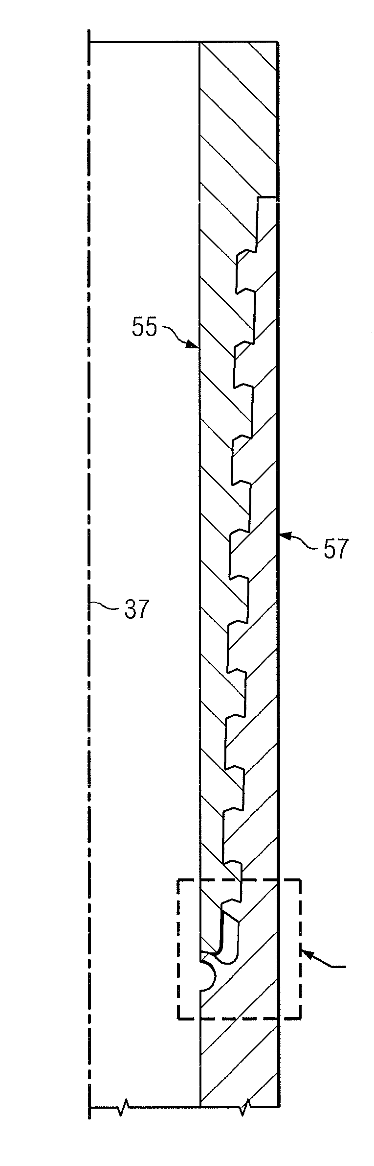
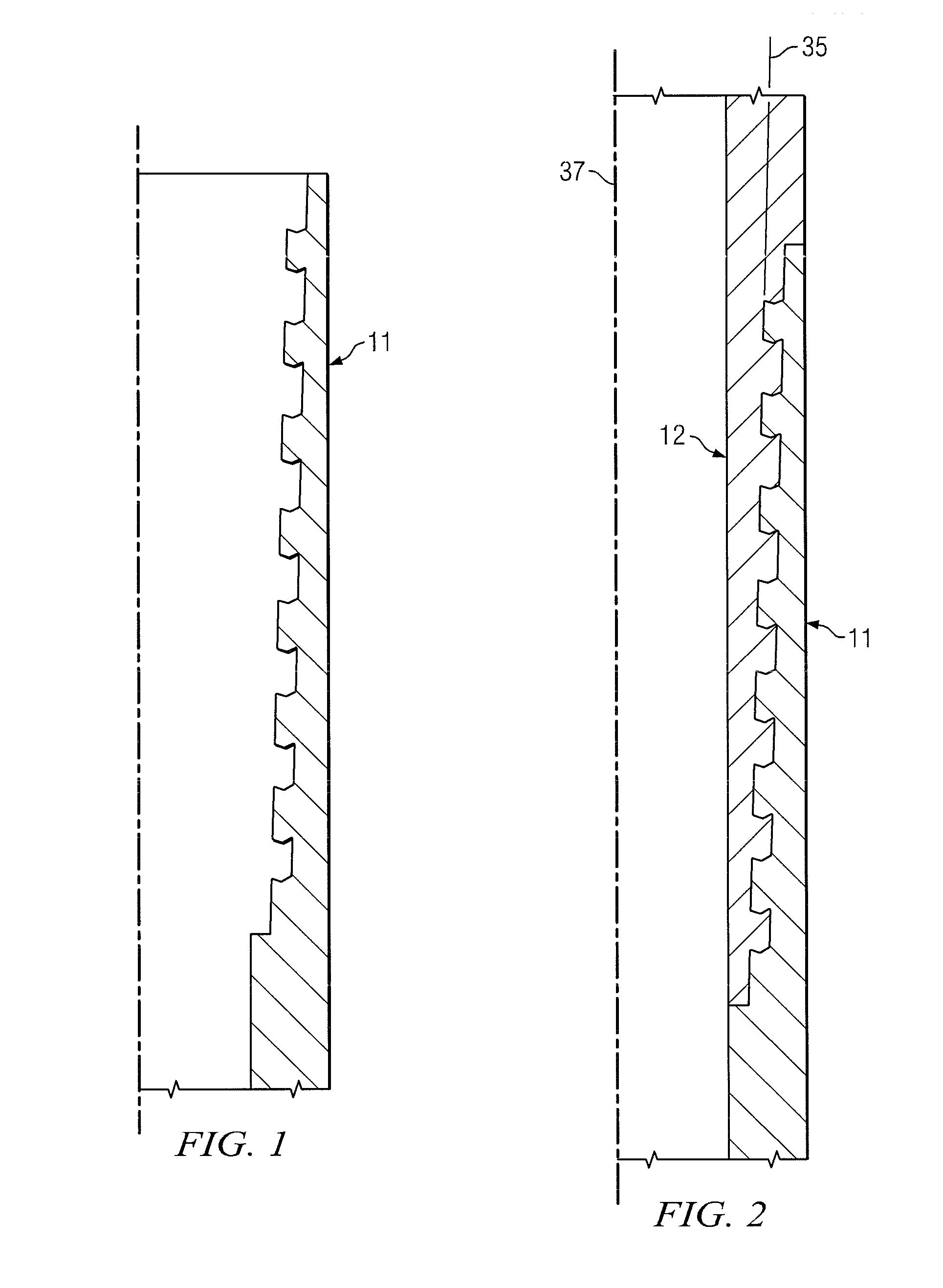
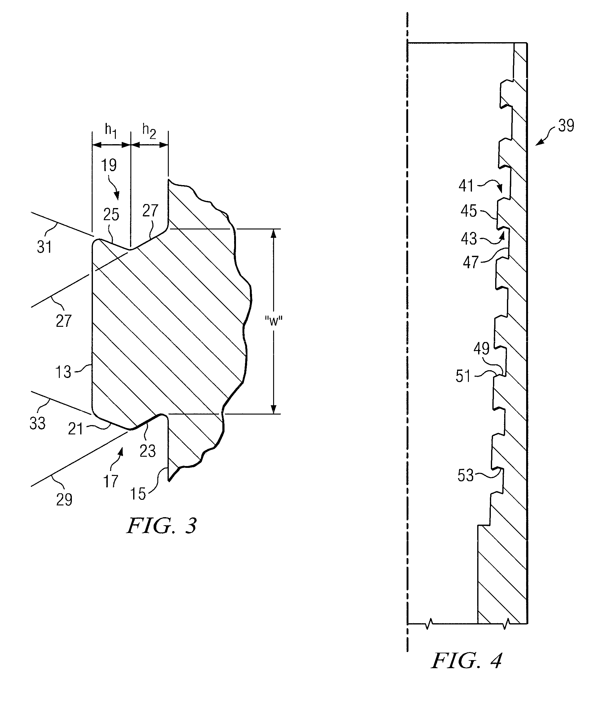
[0029]The flex-seal feature of the invention will now be described with reference to a particular type of thread form which Applicant refers to as the “arrow thread form.” This particular thread form is described in greater detail in Applicant's copending application Ser. No. 61 / 223,874, filed Jul. 8, 2009, entitled “Arrow-shaped Thread Form For Tubular Connections.” However, as will be apparent to those skilled in the art, the flex-seal feature of the present invention could be applied to a variety of types of thread forms known in the prior art. For example, such threaded connections are known for joining flow conduits in an end-to-end relationship to form a continuous flow path for transporting fluid. As discussed above, such threaded connections are used in pipe strings employed for the production of hydrocarbons and other forms of energy from subsurface earth formations. The previously described examples of such pipe strings include drill pipe, well casing and production tubing...


PUM


Abstract

A threaded pipe connection is shown which features a pressure energized flex-seal structure. The connection includes a first box member having a box end, the box end having an end opening defining an interior surface with internal threads, the internal threads being defined by crests and roots and opposing flanks. A second, mating pin member has a pin end with a pin nose, the pin end having an exterior surface with mating external threads, the external threads also having crests and roots and opposing flanks, at least selected ones of which move into engagement with the internal threads of the box when the connection is made up. A flex-seal region is located on the box end interior surface which is designed to engage a cooperating energizing surface on the mating pin end to thereby form a primary containment seal upon make up of the connection.

Description

BACKGROUND OF THE INVENTION[0001]1. Field of the Invention[0002]This invention relates generally to threaded tubular joints or connections and, more specifically, to a tubular joint for connecting the male or pin end of a pipe member to the female or box end of a pipe member in which a tapered radius seal surface provides a pressure energized seal for the connection.[0003]2. Description of the Prior Art[0004]A variety of threaded connections are known in the prior art for joining tubular flow conduits in an end-to-end relationship to form a continuous flow path for transporting fluid. Typical examples of such flow conduits include casing, expandable casing, tubing, drill pipe and risers for oil, gas, water and waste disposal wells, and in horizontal and trenchless drilling applications. In the case of oil field casing and tubing, it is a common practice to use metal pipes of a definite length, with sections of pipe joined to form a string. The string of pipes effectively creates one...

Claims


Application Information

Patent Timeline
IPC IPC(8): F16L15/04
CPCF16L15/06F16L15/004
Inventor LENG, KUO-TSUNG
Owner GANDY TECH
Why Eureka
Try Eureka