Selectable resonant frequency transcutaneous energy transfer system

a transcutaneous energy transfer and resonant frequency technology, applied in the field of inductive power transfer, can solve the problems of reducing the power delivered to the implanted device, reducing the magnitude of the frequency change that can be achieved, and causing power loss, so as to achieve the effect of lowering the power loss

Inactive Publication Date: 2011-05-05
MILLAR INSTR
View PDF5 Cites 123 Cited by
  • Summary
  • Abstract
  • Description
  • Claims
  • Application Information

AI Technical Summary

Benefits of technology

[0006]It is the object of the present invention to provide an inductive power transfer system or a TET system which extends the range of frequencies at which the system resonates and / or lowers the power losses associated with switching reactive components every cycle. Alternatively, it is an object of the invention to provide an improved inductive power transfer system or a TET system, or to at least provide a useful alternative.
[0007]The performance of a TET system may be measured by different objective functions. An example of an objective function is to minimise the power losses. A second example is to maximise the amount of power transferred. A third example is to maintain the maximum temperature below a threshold. A fourth example is to ensure a minimum amount of power is transferred. Combinations of objective functions may be used to control the system. The system may change the objective function at different times in response to command signals or changes in measured parameters.
[0011]Preferably the time that additional discrete controlled reactive components are switched in is much longer than the cycle-by-cycle time of the variable reactive component. The net effect is less power losses caused by lower currents passing through switching elements and lower loses in driving the inputs to the switching devices leading to improved system efficiency.
[0015]In another aspect the invention provides variable reactive components on both the primary circuit and the secondary circuit. The system can operate at different resonant frequencies to maximise performance based on the relevant objective functions.
[0022]In another embodiment, discrete controlled capacitors are switched at both the secondary and primary sides to change from the “normal” to “high power” modes. This enables the system to have two sets of reactive components offering two power levels where power transfer occurs with very high efficiency.
[0026]In one embodiment, the primary conductor which provides a magnetic field to allow power to be induced in the secondary circuit is provided in the form of a coil. The conductor or coil may consist of a number of discrete sections of coil, and sections can be switched in to vary the total inductance. In this embodiment, the reactive element that is adjusted is the inductor (not the capacitor). This is another method of adjusting the resonant frequency and regulating the power flow. A further enhancement allows the selection of sections to provide adjustment to the orientation of the primary coil with respect to the secondary coil without needing to physically move the primary coil mechanism.

Problems solved by technology

A miss-match in resonant frequencies will reduce the power delivered to the implanted device.
Under this scheme, regulating the power requires switching at each cycle of the resonant frequency which creates power losses.
Furthermore, the magnitude of the change in frequency that can be achieved is restricted by the harmonics introduced by the switching processes.

Method used


Image

  • Selectable resonant frequency transcutaneous energy transfer system
  • Selectable resonant frequency transcutaneous energy transfer system
  • Selectable resonant frequency transcutaneous energy transfer system

Examples


Embodiment Construction

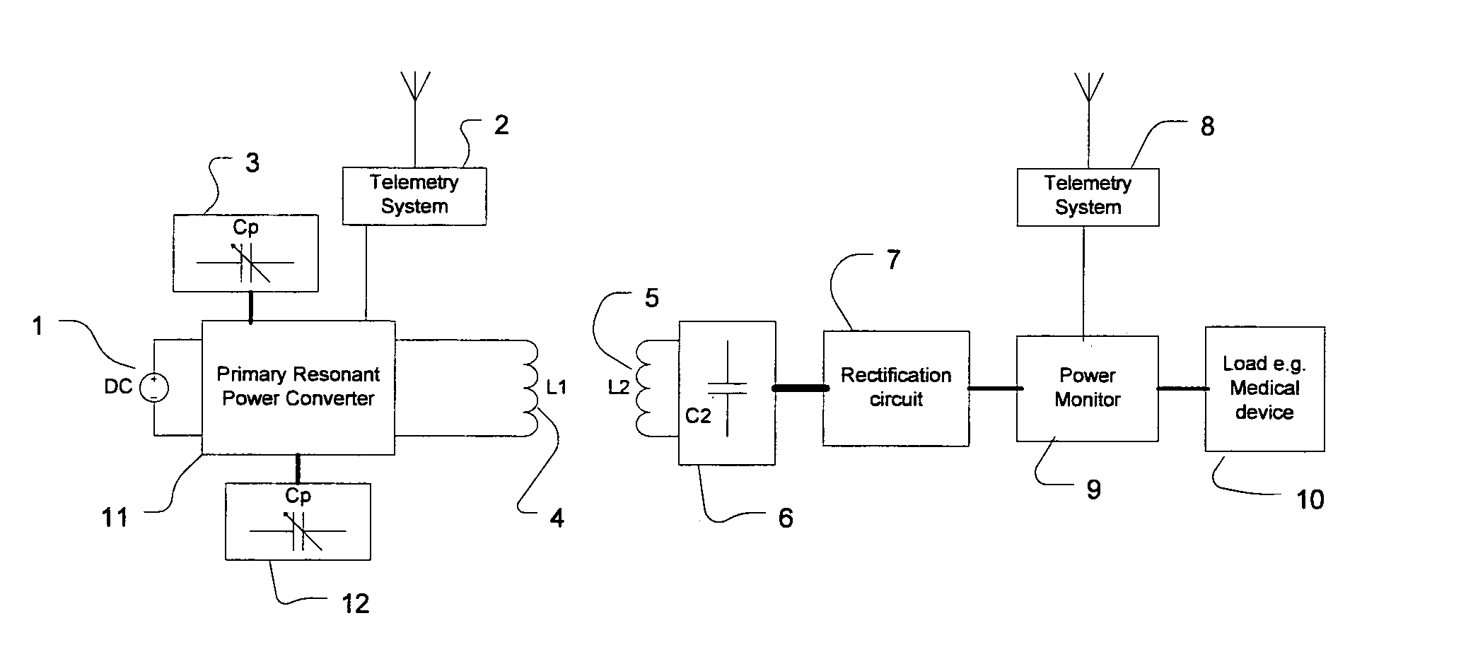
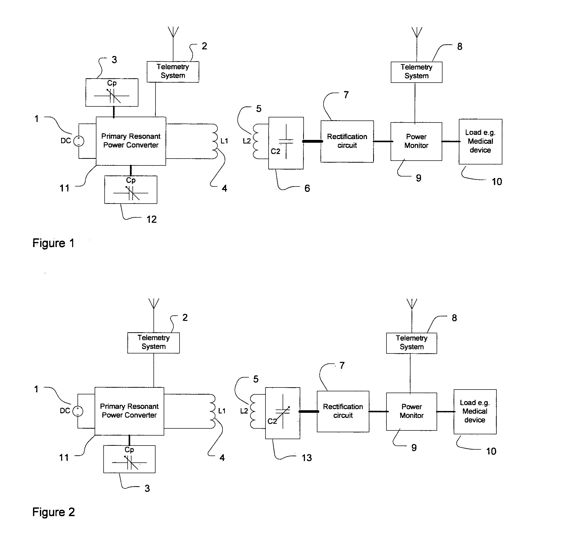
[0043]Referring to the drawings, like reference numerals are used to designate like components throughout the drawing figures. FIG. 1 shows one embodiment of an inductive power transfer (IPT) system in the form of a transcutaneous energy transfer (TED system for providing power from a primary circuit to a secondary, or pick-up, circuit which is closely associated with, and powers, an implanted device. As disclosed in NZ 535012 and NZ 526115, the primary circuit includes a resonant circuit consisting of a tuned conductor capable of providing a required electromagnetic field, such as coil 4. The secondary, or pick-up circuit includes secondary, or a pick-up, coil 5 which is tuned to provide a resonant pick-up circuit. The implanted device is represented by the load 10, and it may be a heart pump and / or battery charging circuit for example, or any other device that consumes electrical power. The implanted device may incorporate other parts of the TET system (5, 6, 7, 8, 9) into the sam...


PUM

PropertyMeasurementUnit
poweraaaaaaaaaa
electromagnetic fieldaaaaaaaaaa
resonant frequencyaaaaaaaaaa

Abstract

An inductive power transfer system includes a number of controllable reactive components (3, 6, 12, 13, 16) that allow the resonant frequency of a primary and / or secondary resonant circuit to be controllably varied to thereby control power available to a load (10).

Description

FIELD OF INVENTION[0001]The invention relates to inductive power transfer, and has particular relevance to adjusting the frequency of resonance of an inductive power transfer system to regulate power delivery and / or maximise system efficiency or power transfer.BACKGROUND[0002]Transcutaneous energy transfer (TET) systems are capable of transferring power across the skin without direct wire connections. This alleviates problems associated with infection at wire exit sites. A TET system will have a primary circuit including an inductive primary coil, located outside the body. The primary circuit generates a magnetic field. A secondary circuit, located inside the body, will include a secondary coil which couples with the magnetic field and the energy available is converted into power for the implanted device.[0003]Because the coupling between the primary and secondary coils is usually low, a resonant circuit is implemented to provide power (voltage or current) amplification. A resonant ...

Claims


Application Information

Patent Timeline
Patent Type & Authority Applications(United States)
IPC IPC(8): H01F38/14
CPCA61B5/0031A61B2560/0219A61F2250/0001A61M1/127H05B6/08A61M2205/8243A61N1/3787H02J5/005H05B6/06A61M2205/3507H02J50/12H02J50/402H02J50/80H02J2310/23A61N1/08A61N1/40H02J3/34
Inventor BUDGETT, DAVID
Owner MILLAR INSTR
Why Eureka
Try Eureka