
Diffractive lens and image pickup device using the same

a pickup device and diffractive lens technology, applied in the direction of diffraction gratings, optics, instruments, etc., can solve the problem of large flare of resultant color images, and achieve the effect of reducing flare, increasing the first-order diffraction efficiency of light incident on the second group of diffraction steps, and minimizing flar

Active Publication Date: 2011-05-05
PANASONIC CORP
View PDF10 Cites 9 Cited by
  • Summary
  • Abstract
  • Description
  • Claims
  • Application Information

AI Technical Summary

Benefits of technology

"The present invention relates to a diffractive lens that can achieve high resolution in a wide angle range by minimizing unnecessary diffracted light and loss of light. The invention also relates to an image capture device that uses this diffractive lens. The diffractive lens has a concentric diffraction grating portion on the surface of an aspheric lens, which can reduce various aberrations such as chromatic aberration and field curvature. However, the use of a diffractive lens in a wide angle range can produce flare, which causes a problem in capturing images. To solve this problem, the invention proposes a technique for reducing the wavelength dependence of the diffraction efficiency of a particular order by applying a protective coating to the diffraction grating portion. The resulting diffractive lens produces only a few unnecessary diffracted rays and is less likely to cause flare."

Problems solved by technology

However, if light falling within the entire visible radiation range (i.e., in the wavelength range of 400 nm through 700 nm) is made to be incident on an aspheric diffractive lens, on which a diffraction grating portion such as the one shown in FIG. 9 has been formed concentrically, the resultant color image will have a lot of noticeable flare.

Method used


Image

  • Diffractive lens and image pickup device using the same
  • Diffractive lens and image pickup device using the same
  • Diffractive lens and image pickup device using the same

Examples


embodiments

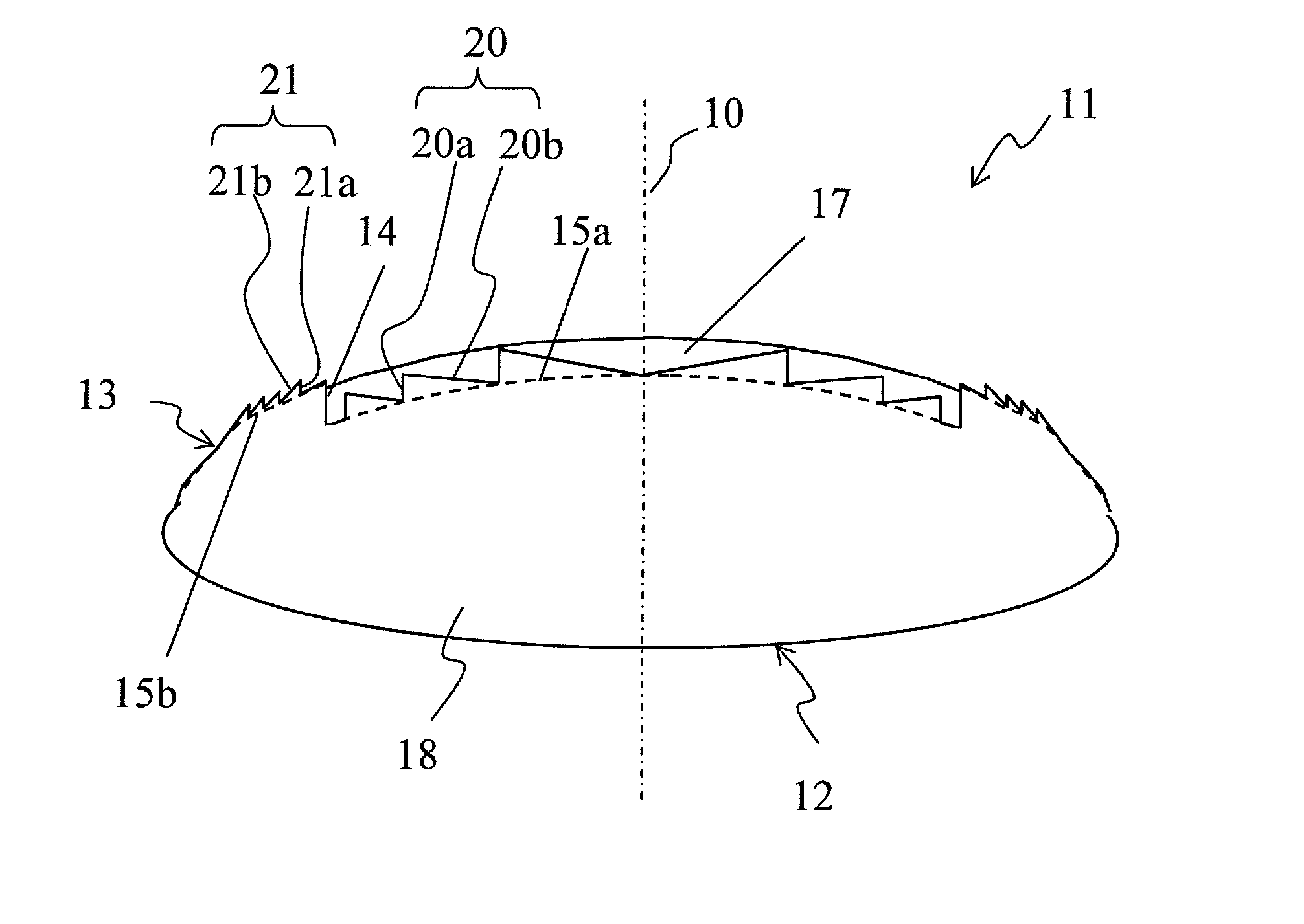
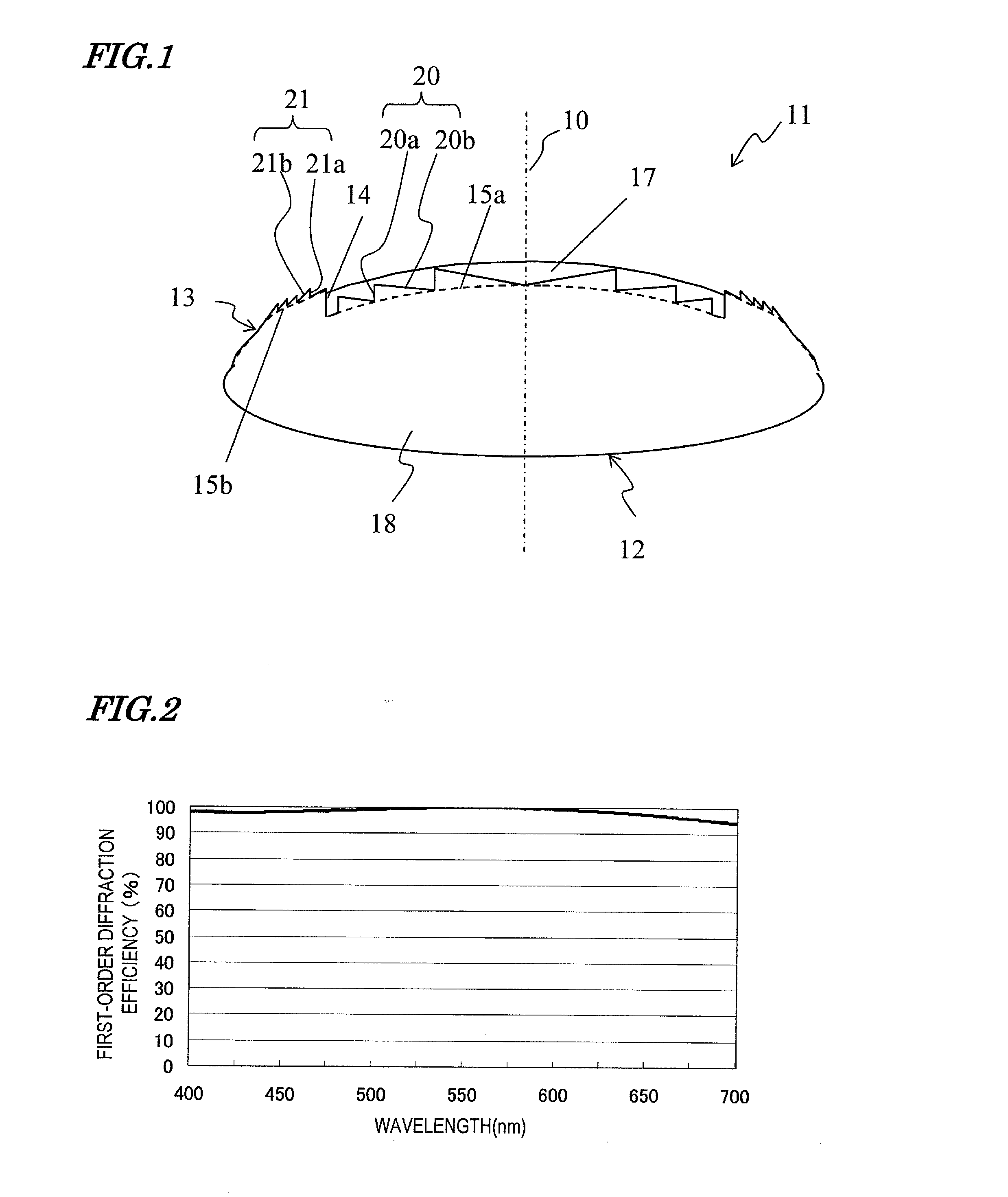
[0037]FIG. 1 is a cross-sectional view illustrating a diffractive imaging lens 11 as a specific preferred embodiment of the present invention. The diffractive imaging lens 11 of this preferred embodiment includes a lens base 18 and a protective coating 17. The lens base 18 has first and second aspheric surfaces 12 and 13. The first surface 12 will face toward the subject, while the second surface 13 will face away from the subject (i.e., face toward the place where the incoming light is imaged). And the second surface 13 has first and second groups of diffraction grating portions 20 and 21 and each group has a concentric ring pattern in plan view. The second group of diffraction grating portions 21 is located farther away from the optical axis 10 than the first group of diffraction grating portions 20 is. The protective coating 17 does cover the first group of diffraction grating portions 20 but does not cover the second group of diffraction grating portions 21.

[0038]The first and s...


PUM


Abstract

A diffractive lens 11 according to the present invention includes: a lens base 18, which has a second surface 13 with first and second groups of diffraction grating portions 20 and 21; and a protective coating 17, which is arranged on the first group of diffraction grating portions 20. The first group of diffraction grating portions 20 has a first group of diffraction steps and the second group of diffraction grating portions 21 has a second group of diffraction steps, which is lower in height than the first group of diffraction steps. One of the respective materials of the base 18 and the protective coating 17 has a higher refractive index and a greater Abbe number than the other material. And the second group of diffraction steps is not covered with the protective coating 17.

Description

TECHNICAL FIELD[0001]The present invention relates to a diffractive lens that realizes high resolution in a wide angle range by minimizing production of unnecessary diffracted light and loss of light, and also relates to an image capture device that uses such a lens.BACKGROUND ART[0002]A diffractive lens, which has a concentric diffraction grating portion on the surface of an aspheric lens, is known as a lens that would realize higher image capturing performance than an aspheric lens. By achieving not just the refraction effect of an aspheric lens but also diffraction effect, a diffractive lens can reduce significantly various kinds of aberrations such as chromatic aberration and field curvature. Particularly with a diffraction grating portion, of which the cross section is either blazed or consisting of fine steps that are inscribed to each other in a blazed pattern, the diffraction efficiency of a particular order with respect to a single wavelength can be increased to almost 100%...

Claims


Application Information

Patent Timeline
Patent Type & Authority Applications(United States)
IPC IPC(8): G02B5/18
CPCG02B13/003G02B27/4211G02B5/1814G02B13/06
Inventor KORENAGA, TSUGUHIROANDO, TAKAMASA
Owner PANASONIC CORP
Learn More