Decorative piece made by inlay

a technology of decorative pieces and inlay, applied in the field of decorative pieces, can solve the problems of complex type of methods, extremely slow, and heavy materials, and achieve the effect of simple operation

Active Publication Date: 2011-05-05
OMEGA SA
View PDF6 Cites 35 Cited by
  • Summary
  • Abstract
  • Description
  • Claims
  • Application Information

AI Technical Summary

Benefits of technology

[0009]The invention concerns a decorative piece that overcomes the aforementioned drawbacks of the prior art by proposing a decorative piece obtained by inlay work that is simple to perform, very reproducible and compatible with most structures that can be inlaid.

Problems solved by technology

However, this type of method is complex and extremely slow.
Indeed, the method requires a heavy material and includes numerous steps requiring extremely precise parameter control for the marking to be successful.
Thus deviations from the method and thus the heterogeneity of the manufactured pieces can thus easily occur.
Finally, this electroforming method cannot deposit chemical elements beyond a certain thickness, which limits the depth of the hollows.
However, one drawback of this method is that shrinkage phenomenon is inevitable when the liquid alloy solidifies in crystalline form.
This phenomenon then either causes the inlaid elements to come loose, or significant mechanical stress on the inlaid elements that may cause them to break.
This method can only inlay elements whose melting point is higher than that of metal.
In the particular case of the ceramic-metal system, an additional limit of this method is the long process time.
Indeed, the poor resistance of ceramic to thermal shocks involves slow heating and cooling speeds.

Method used


Image

  • Decorative piece made by inlay
  • Decorative piece made by inlay
  • Decorative piece made by inlay

Examples


first embodiment

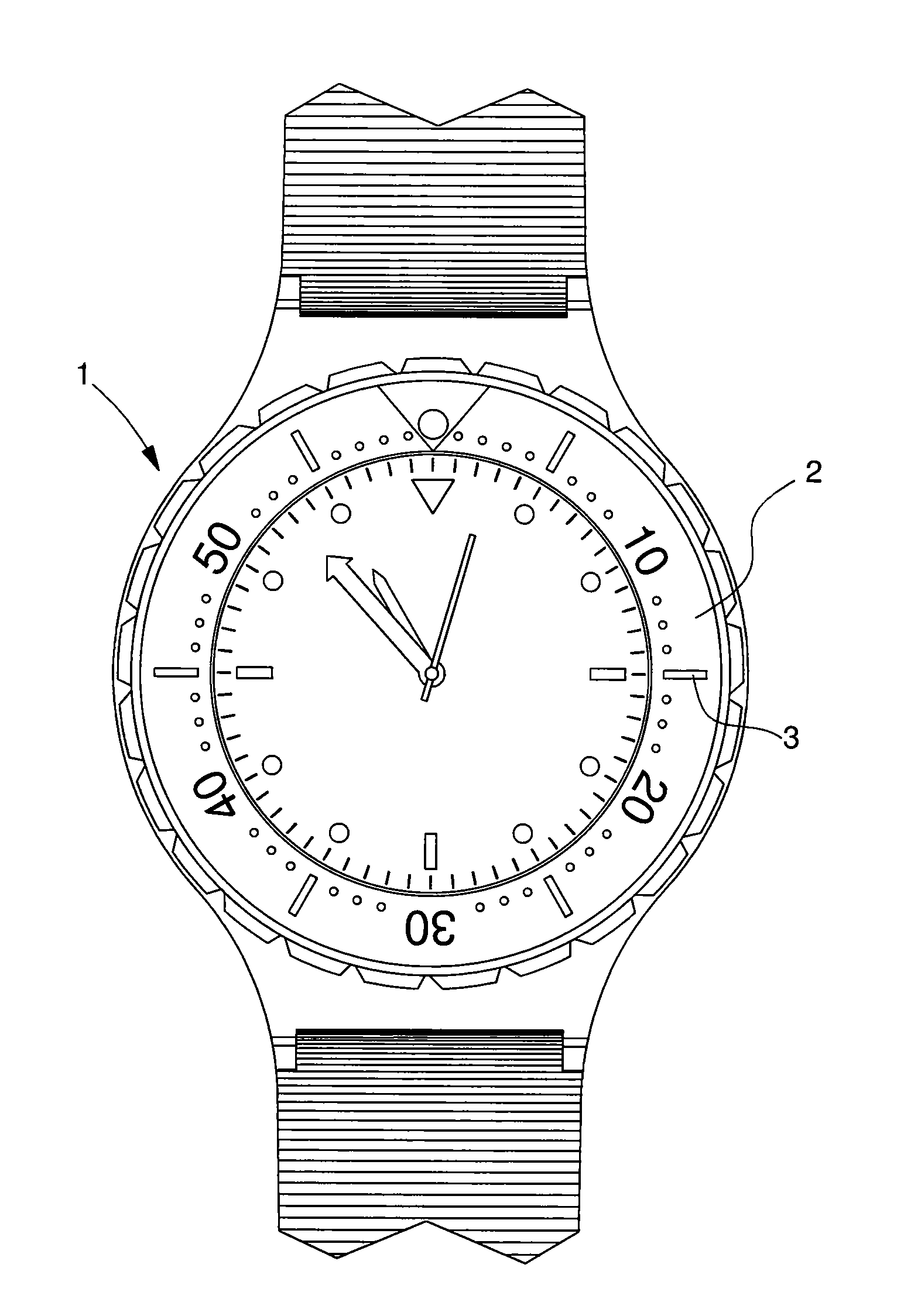
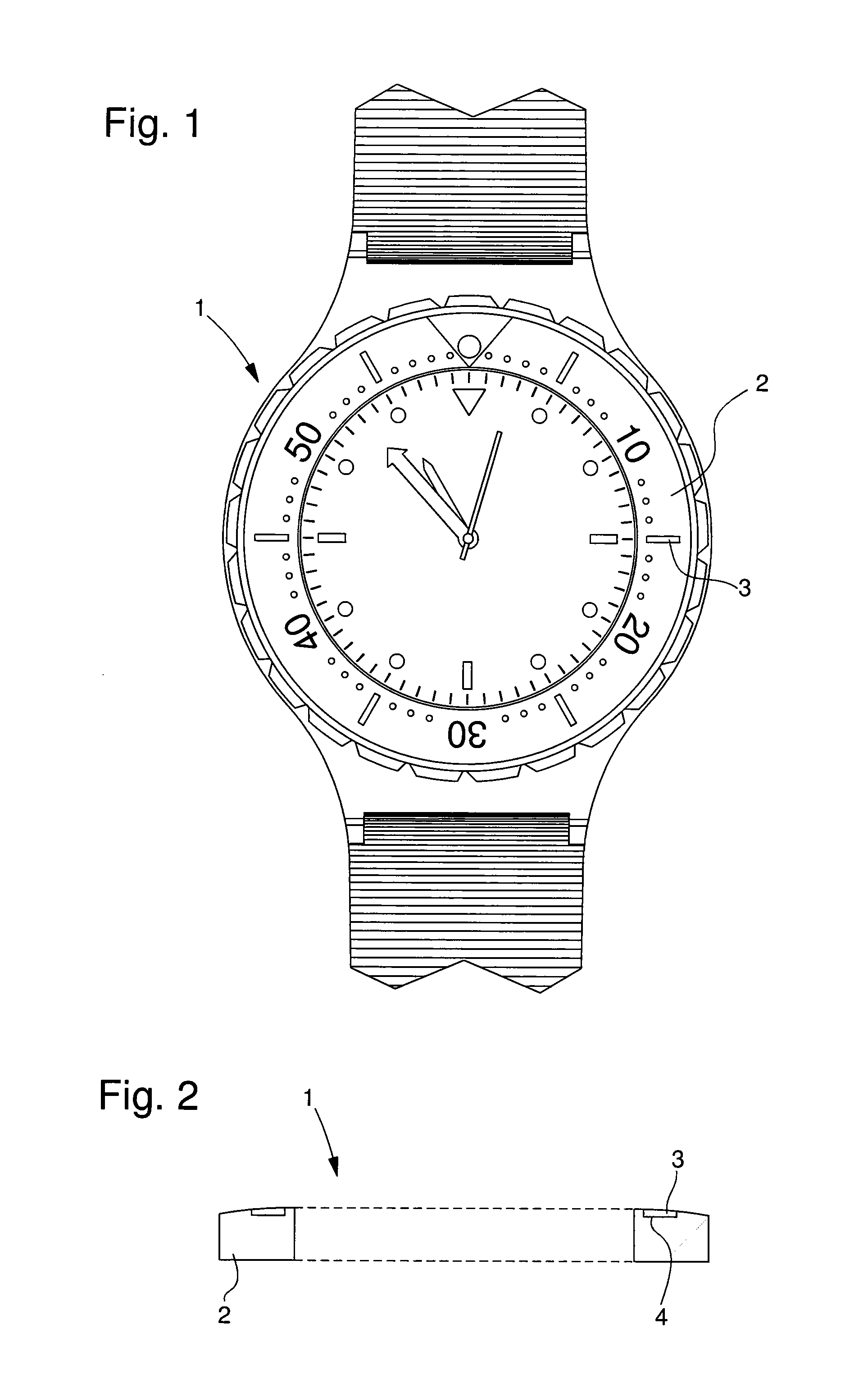
[0031]FIGS. 1 and 2 show a first embodiment according to the invention. In this embodiment, decorative piece 1 may be, for example, a watch bezel inlaid with signs. It is clear that the bezel includes an annular body forming support 2 in which signs, forming aesthetic elements 3, are inlaid. The bezel may be made, for example, of ceramic material and may include recesses or hollows 4, shown in FIG. 2, arranged on said bezel for receiving the inlaid signs. This inlay advantageously enables said signs to be partially covered and thus gives the product a longer life time by preventing the constituent parts 2, 3 of decorative piece 1 from becoming detached.

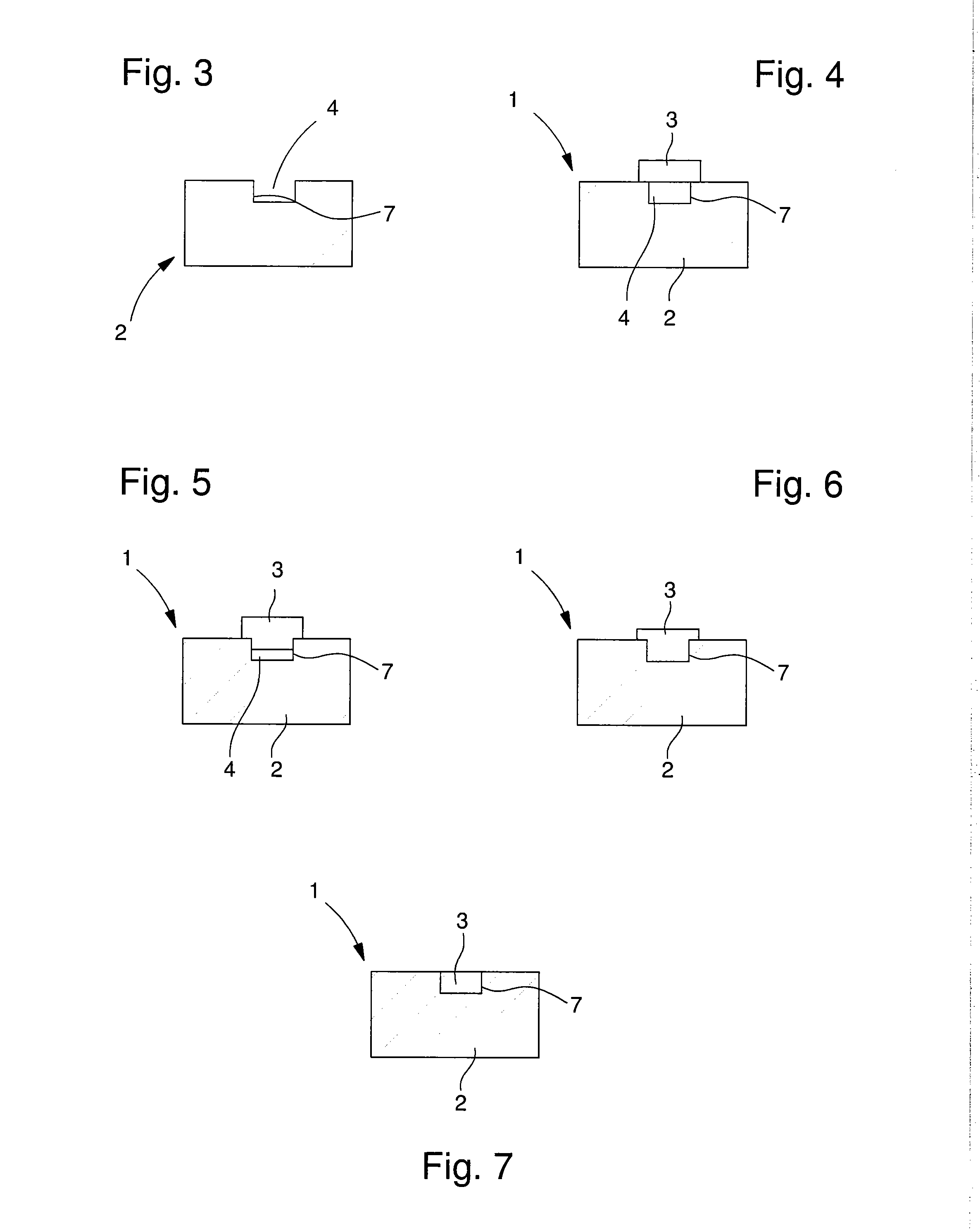
[0032]Each hollow 4 then takes the form of a design corresponding to the sign to be inlaid and has sides or lateral walls 7, preferably approximately perpendicular to the visible surface. Hollows 4 are filled so that the signs project, are flush with or form a hollow relative to the annular body.

[0033]Thus, to fill said hollows 4, the...

second embodiment

[0045]Thus, to make decorative piece 1 according to this second embodiment, the method is the same as that described previously, i.e. the elements to be inlaid are pressed onto support 2. This method is described in FIGS. 11 to 14. In this case, it is support 2 that is heated to make it viscous and to inlay therein said aesthetic elements 3. Thus, as seen in FIG. 11, aesthetic element 3 is placed on said support 2: the assembly is then heated and pressed in a hot press as seen in FIG. 12. In the example shown in FIGS. 11 to 14, the pressure is localised on the element to be inlaid alone. It is clear that the pressure can be exerted over the entire decorative piece. This operation is carried out until aesthetic element 3 is partially covered in said support 2 as seen in FIG. 13. Once the amorphous material has cooled, polishing is carried out to remove the surplus material, as shown in FIG. 14.

[0046]According to a first variant, aesthetic elements 3 can be made of crystalline metal. ...

third embodiment

[0048]According to the invention, aesthetic elements 3 are made of enamel. A mixed decorative piece 1 can be made of amorphous material-enamel, offering a particular visual appearance while being simpler to produce. Indeed, to inlay enamel elements on a crystalline metal, the features of the metal, such as, amongst others, the melting point of the metal and the expansion coefficient, mean that the inlay is complex. This is not the case for an amorphous material for which the temperature at which the material becomes viscous is lower, allowing inlay work at lower pressure. This lower pressure exerted on the enamel then means that the enamel does not break.

[0049]For these three variants, the viscosity of the amorphous material forming support 2 enables said material to creep into every corner thereby solidly securing aesthetic elements 3 in support 2.

[0050]Of course, the above variants are not limited to inlaying a single aesthetic element. Indeed, several aesthetic elements, which ma...


PUM

PropertyMeasurementUnit
thicknessaaaaaaaaaa
metallicaaaaaaaaaa
areaaaaaaaaaaa

Abstract

The present invention concerns a decorative piece (1) including a first (2) and a second part (3). The second part (3) is secured in the first part (3) by inlay. The invention is characterized in that at least one of the parts (2, 3) is made of an at least partially amorphous material.

Description

[0001]This is a National Phase Application in the United States of International Patent Application PCT / EP2009 / 057737 filed Jun. 22, 2009, which claims priority on European Patent Application No. 08158771.9 of Jun. 23, 2008. The entire disclosures of the above patent applications are hereby incorporated by reference.[0002]The present invention concerns a decorative piece. This decorative piece includes a first part and a second part. The second part is inlaid in the first.BACKGROUND OF THE INVENTION[0003]In the prior art there are known decorative pieces that are to be added to a portable object such as a watch and that consist of an aesthetic element inlaid on the elements of said portable object. For example, there exist watch bezels decorated with patterns such as signs. These bezels, which can be made of ceramic, can be marked in various ways and with various materials, such as gold, silver or platinum. The marking may be embossed or at a depth. In the case of deep marking, this...

Claims


Application Information

Patent Timeline
Patent Type & Authority Applications(United States)
IPC IPC(8): G04B47/04B44C1/26B23P11/00G04D3/00
CPCB21J1/006B44C1/26B44C5/0415G04B19/103Y10T428/22G04B37/0008Y10T29/49579Y10T29/49826G04B19/18G04B19/10G04B19/28A44C27/002A44C27/003
Inventor WINKLER, YVESBOURBAN, STEWESDIONNE, JEAN-FRANCOIS
Owner OMEGA SA
Why Eureka
Try Eureka