Laminated body and circuit wiring board

a circuit wiring and laminated body technology, applied in the field of laminated bodies, can solve the problems of difficult to achieve miniaturization and densification, and low reliability of laminated bodies using the above adhesive, etc., to achieve high adhesiveness and improve reliability.

Inactive Publication Date: 2011-05-05
SULFUR CHEM INST INC
View PDF10 Cites 23 Cited by
  • Summary
  • Abstract
  • Description
  • Claims
  • Application Information

AI Technical Summary

Benefits of technology

[0035]The present invention is capable of solving, all at once, the controversial points of the prior arts such as the adhesiveness to the board of which the surface roughness is large, alleviation of the stress concentration, an improvement in the reliability, the high adhesiveness (especially, that of a conductor layer), the heat resi...

Problems solved by technology

The conventional bonding method, however, necessitates appropriately selecting the adhesives suitable for kinds of adherends, and yet causes a problem that a bonding force declines in final commodities due to an evil influence by a shape keeping function that the adhesive itself has, and the laminated body using the above adhesive is lacking a reliability (strength, endurance, etc.).
In addition, with the case of the physical bonding to be typified by the use of the above adhesive, it is known that adhesiveness is enhanced owing to an anchor effect all the more as surface roughness of the board becomes larger, and on the other hand, when the board of which the surface roughness is large is used, particularly for the laminated body to be employed in the field demanding a high precision such as the circuit wiring board, a problem surfaces that it is difficult to attain miniaturization and densification thereof, and the laminated body is lacking in reliability.
As it is, the conventional chemical bonding methods takes it as a...

Method used


Image

  • Laminated body and circuit wiring board
  • Laminated body and circuit wiring board
  • Laminated body and circuit wiring board

Examples


exemplary example 1

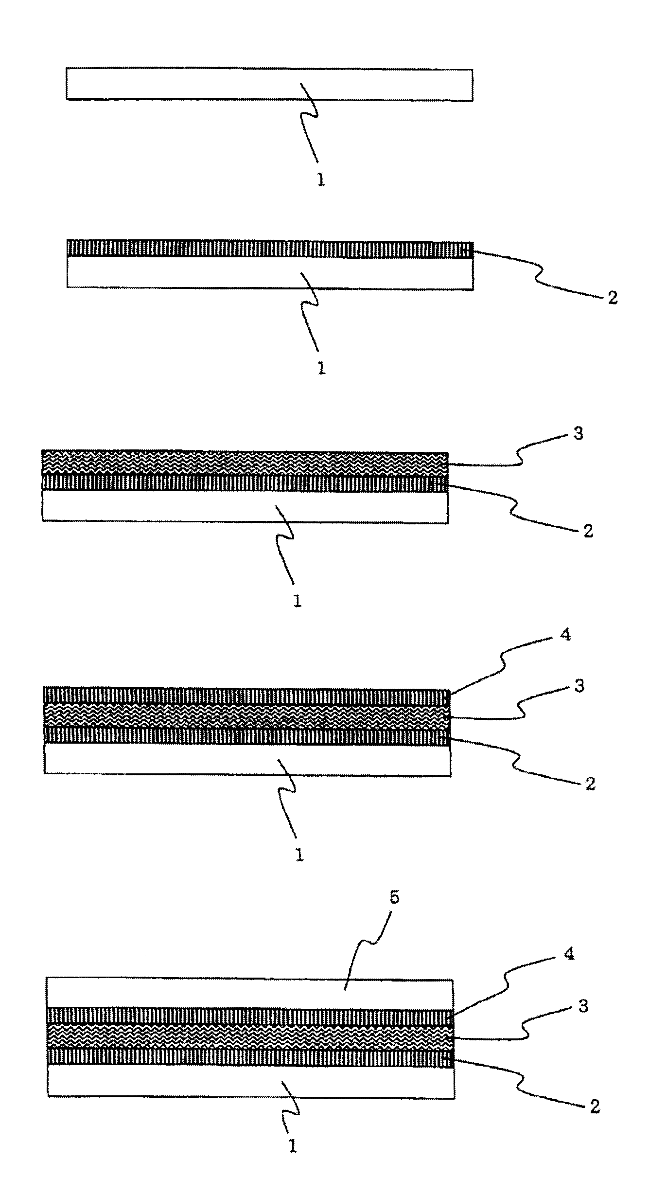
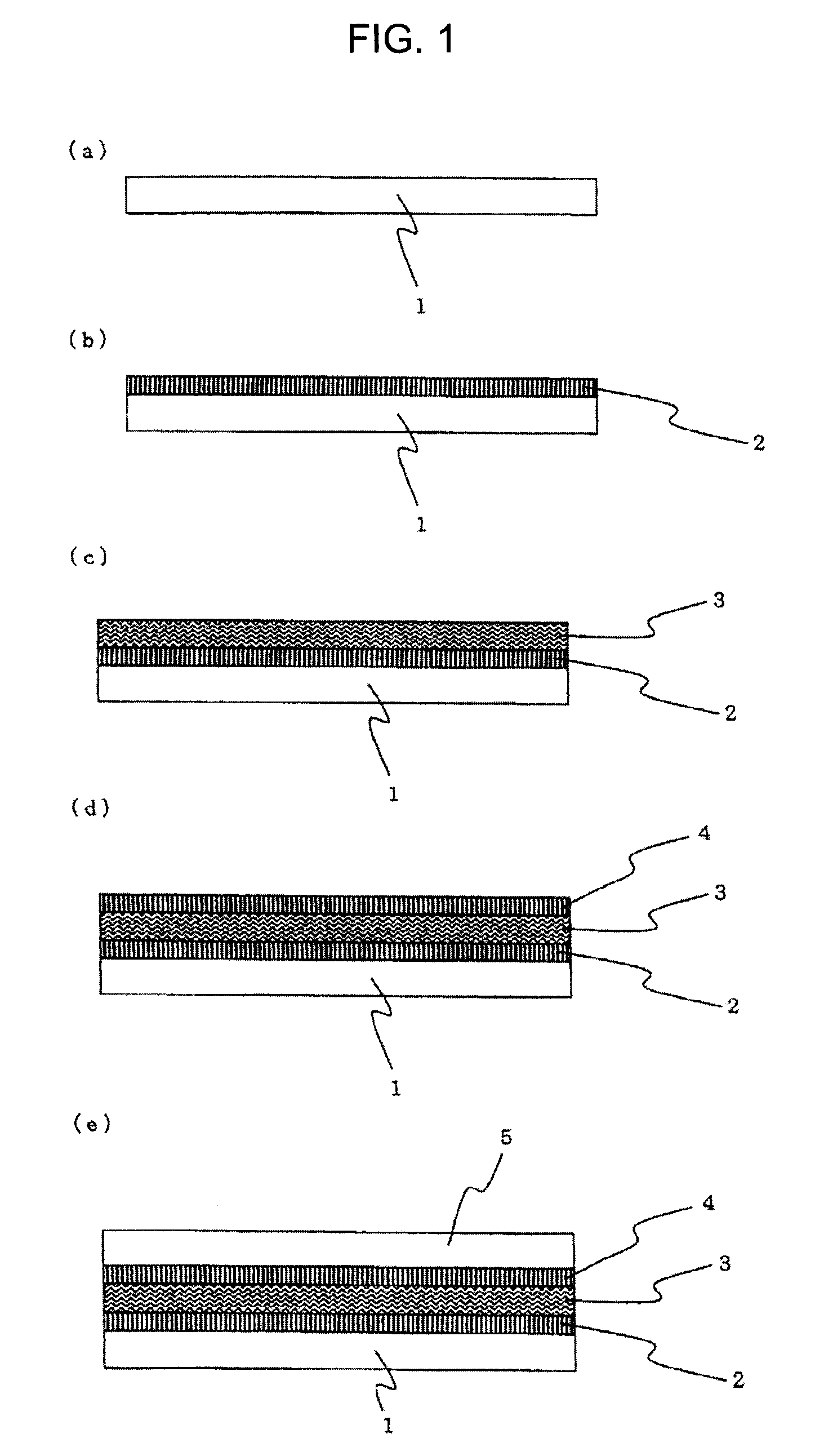
Manufacturing a Board (I) Subjected to a Hydroxylation Treatment

[0179]The board (I) subjected to the hydroxylation treatment is manufactured by using an aluminum plate (1×30×50 mm, made of the Nilaco corporation, and hereinafter, sometimes referred to as “Al”) as the board, and performing the corona discharge treatment of which a number of roundtrips is three with an output power of 13 kW at a speed of 2 m / minute using the corona discharging apparatus made by Kasuga electric works Ltd).

Manufacturing the Board Having the Molecular Adhesive Linked Hereto (II)

[0180]The board (II) having the molecular adhesive (TES) linked hereto was obtained by immersing the obtained board (I) in a 95% water / ethanol (0.2% by weight) solution of 6-(3-(triethoxysilyl)propylamino)-1,3,5-triazine-2,4-dithiol monosodium (TES) for five minutes, thereafter heating it in the oven for 10 minutes at a temperature of 150° C., and performing the ethanol cleaning / dryer drying.

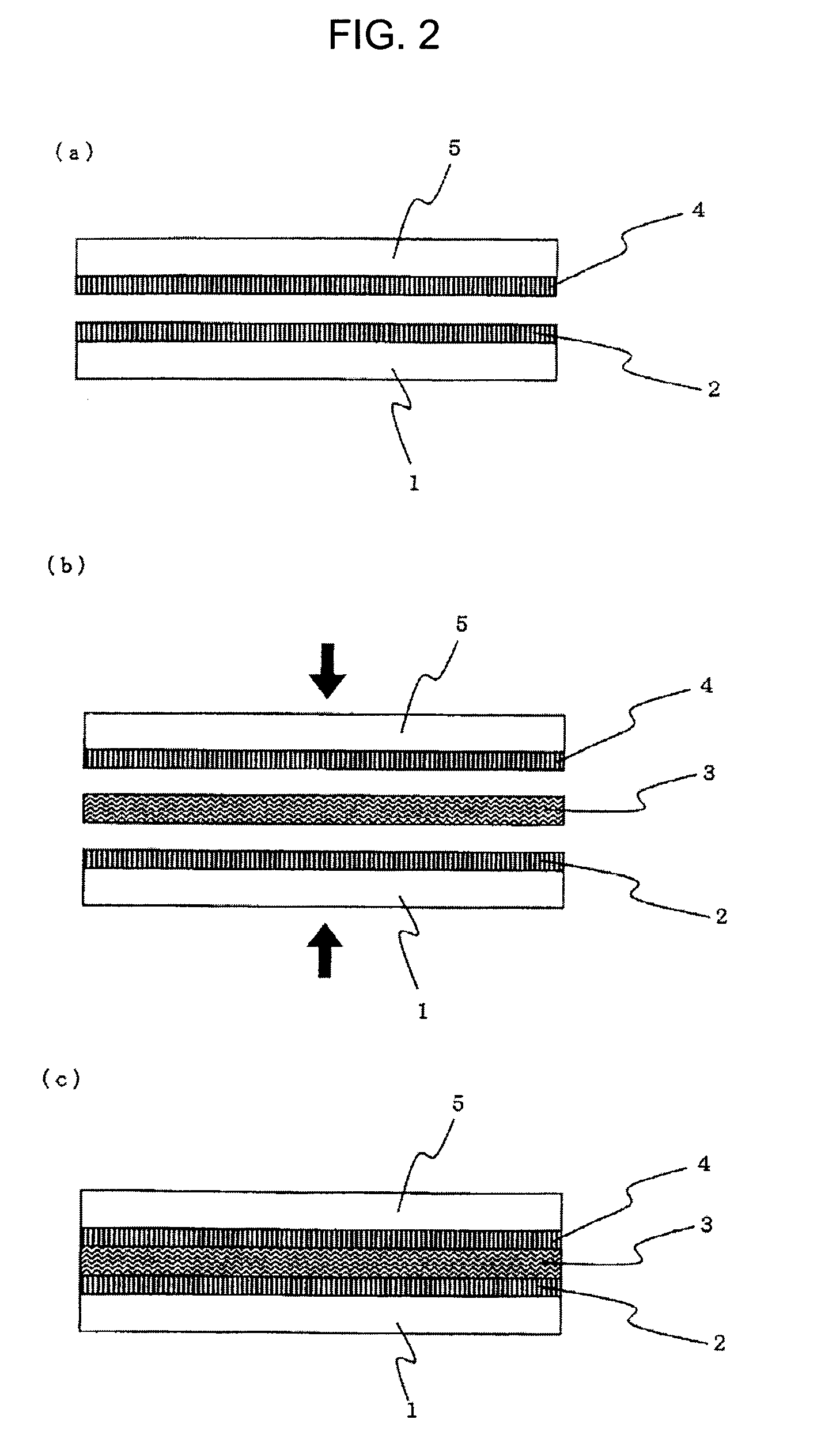
Manufacturing the Bonded Product (III) ...

exemplary example 2

[0185]The laminated body (V) was obtained similarly to the exemplary example 1 except that an alumina board (30×50×3 mm, hereinafter, sometimes referred to as “alumina”) was used as the board instead of the aluminum plate.

exemplary example 3

[0186]The laminated body (V) was obtained similarly to the exemplary example 1 except that a glass epoxy resin plate (0.2×30×50 mm, FR-4; made by Panasonic Electric works and hereinafter, sometimes referred to as “EP”) was used as the board instead of the aluminum plate.


PUM

PropertyMeasurementUnit
Lengthaaaaaaaaaa
Temperatureaaaaaaaaaa
Timeaaaaaaaaaa

Abstract

Provided is a laminated body which solves, all at once, the issues of conventional methods, such as adhesiveness to a board having low surface roughness, stress concentration relaxing, reliability improvement, high adhesiveness (especially, that of a conductor layer), heat resistance, almighty characteristics (being adherable irrespective of the type of an adhesive), in manufacture of laminated bodies. The laminated body is formed by having an entropically elastic molecular adhesive layer between two boards, and the entropically elastic molecular adhesive layer is composed of an entropically elastic material layer, and a layer of a molecular adhesive having a group which can be bonded to the entropically elastic material layer.

Description

TECHNICAL FIELD[0001]The present invention relates to a laminated body that is manufactured by forming an entropy elastic molecular bonding layer between two boards, wherein the above elastic molecular bonding layer is composed of an entropy elastomer layer and a molecular adhesive layer. The present invention relates to electronic mounting parts, precision machine parts, building strictures, circuit wiring boards, decorative plating commodities, and bonded complex commodities each of which is composed of the above laminated body.BACKGROUND ART[0002]Conventionally, the laminated body employing various adhesives has been put into practical use in the technological field such as the laminated body of the board and the circuit wiring board. The conventional bonding method, however, necessitates appropriately selecting the adhesives suitable for kinds of adherends, and yet causes a problem that a bonding force declines in final commodities due to an evil influence by a shape keeping fun...

Claims


Application Information

Patent Timeline
IPC IPC(8): B32B7/12B32B15/06B32B25/04B32B37/12
CPCB32B7/12B32B15/06B32B15/08B32B25/04B32B25/14H05K2201/0133B32B27/32C09J121/02H05K3/386H05K3/389B32B27/06Y10T428/31663
Inventor MORI, KUNIOMATSUNO, YUSUKE
Owner SULFUR CHEM INST INC
Why Eureka
Try Eureka