Burning element and burner with a corrosion-resistant insert

a burner and insert technology, applied in the direction of corrosion prevention fuel injection, combustion types, lighting and heating apparatuses, etc., can solve the problems of affecting the availability of the burner, the emission value of the burner is considerably worse, and the hole is plugged, so as to prevent the formation of scale, improve the emission value of the burner, and prevent the effect of expensive and effective prevention

Inactive Publication Date: 2011-05-05
SIEMENS AG
View PDF40 Cites 2 Cited by
  • Summary
  • Abstract
  • Description
  • Claims
  • Application Information

AI Technical Summary

Benefits of technology

[0008]The burner element according to the invention comprises a surface which potentially comes into contact with a fuel. The burner element also comprises a base metal and a corrosion-resistant material, the surface potentially coming into contact with a fuel being made of said corrosion-resistant material. This prevents the formation of deposits, in particular of iron sulfide scale, on the surface potentially coming into contact with a fuel, thus ensuring compliance with emission limit values. It also enables the costs of cleaning or installing a new burner to be saved.
[0013]Using the burner carrier flange according to the invention, the fuel used can flow through the opening of the insert. As the insert is made of corrosion-resistant material, the fuel does not come into contact with the base metal, thereby preventing scale formation.
[0014]The burner according to the invention comprises an inventive burner element as described above. Said burner can be, for example, a pilot burner. The pilot burner can comprise, for example, nozzle holes one millimeter in diameter. The burner according to the invention basically has the same advantages as the described burner element according to the invention. With the aid of the present invention, the formation of deposits, in particular of iron sulfide scale, inside a burner can be inexpensively and effectively prevented. In addition, the present invention improves the emission values of the burner.

Problems solved by technology

The iron sulfide scale forming inside the burner may flake off and in some cases cause plugging of the holes through which the fuel is injected into a combustion chamber.
Plugging of said holes results in uneven combustion, thereby considerably worsening in particular the emission values of the burner in question.
The availability of the burner affected or more specifically the associated combustion chamber is impaired in this case.
However, cleaning is very time-consuming.
In such cases, therefore, a complete set of new burners generally has to be installed which is very expensive.
Although the problems described only occur on machines which are operated with pre-heating, these machines are being increasingly used.
High additional costs resulting from the possible formation of iron sulfide scale are therefore to be expected.
However, these materials are much more expensive than the 16Mo3 steel used hitherto.

Method used


Image

  • Burning element and burner with a corrosion-resistant insert
  • Burning element and burner with a corrosion-resistant insert
  • Burning element and burner with a corrosion-resistant insert

Examples


Embodiment Construction

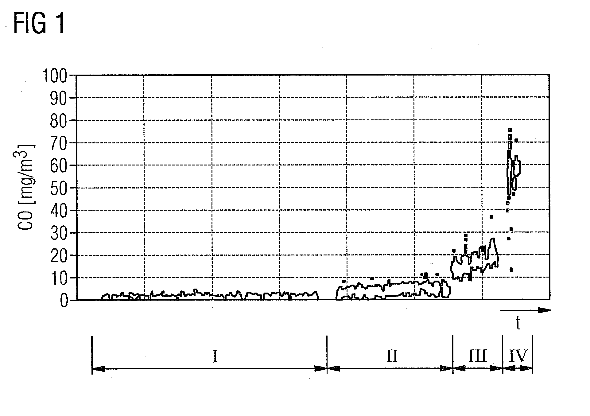
[0022]An exemplary embodiment of the present invention will now be explained in greater detail with reference to FIGS. 1 to 6. FIG. 1 shows the CO emission values of a conventional burner as a function of the operating time. Plotted on the x-axis of the graph shown in FIG. 1 is the date of the CO emission measurement. Plotted on the y-axis are the measured CO emission values in milligrams per cubic meter.

[0023]The graph shows the CO emission values for the burner in question over a period of time, subdivided into four sections I, II, III, IV. After a longer operating section I with extremely low emission values, the latter increased continuously in the second section II, but were mainly below 10 mg / m3. In the subsequent time section III, the CO emission values increased more strongly than in section II and were mainly between 10 and 30 mg / m3. In the fourth time section IV, CO emission values mainly between 40 and 80 mg / m3 were measured.

[0024]The measurement shown in FIG. 1 shows tha...


PUM


Abstract

A burner carrier flange and a burner with such a burner carrier flange are provided. A surface of the burner carrier flange potentially comes into contact with fuel. The burner carrier element includes a base material and a corrosion-resistant material and the surface that potentially comes into contact with fuel is made of the corrosion-resistant material.

Description

CROSS REFERENCE TO RELATED APPLICATIONS[0001]This application is the US National Stage of International Application No. PCT / EP2009 / 051432 filed Feb. 9, 2009, and claims the benefit thereof. The International Application claims the benefits of European Patent Application No. 08002769.1 EP filed Feb. 14, 2008. All of the applications are incorporated by reference herein in their entirety.FIELD OF INVENTION[0002]The present invention relates to a burner element and a burner which are equipped with a corrosion-resistant insert.BACKGROUND OF INVENTION[0003]Internally, particular parts of a burner typically come into contact with fuel. The chemical reaction of sulfur compounds (H2S) contained in the fuel with the base metal of the burner may cause iron sulfide scale to form inside the burner. The base metal of the burner is typically steel, e.g. 16Mo3 steel. The iron sulfide scale forming inside the burner may flake off and in some cases cause plugging of the holes through which the fuel ...

Claims


Application Information

Patent Timeline
Patent Type & Authority Applications(United States)
IPC IPC(8): F23D11/36
CPCF23D11/36F23D2213/00F23R3/283F23M5/025F23D2900/00018F01D25/007F02M2200/05F23C5/02
Inventor BOTTCHER, ANDREASKUNADT, THOMASPFEIFFER, ELMARWORZ, ULRICH
Owner SIEMENS AG
Why Eureka
Try Eureka