Dialysis device

a technology of dialysis device and dialysis chamber, which is applied in the direction of machines/engines, flexible member pumps, positive displacement liquid engines, etc., can solve the problems of high power consumption and heat generation, system to be often very bulky and heavy and cumbersome to transport, and unpleasant noise levels

Inactive Publication Date: 2011-05-05
GAMBRO LUNDIA AB
View PDF11 Cites 59 Cited by
  • Summary
  • Abstract
  • Description
  • Claims
  • Application Information

AI Technical Summary

Benefits of technology

[0005]It has now been found that peristaltic pumps of linear build with piezoelectric actuat

Problems solved by technology

Disadvantages of the radial peristaltic pumps used up to now are their installation size and weight, which contribute to the considerable space requirement and weight of conventional dialysis systems, causing these systems t

Method used


Image

  • Dialysis device
  • Dialysis device
  • Dialysis device

Examples


Embodiment Construction

[0013]Preferred embodiments of the present invention will now be described in more detail with reference to the accompanying drawings.

[0014]Peristaltic pumps of linear build with piezoelectric actuators (hereinafter abbreviated as “piezo pumps”) which are suitable for use in the dialysis systems of the present invention are known in the art in principle. For instance, pumps as disclosed in GB-A 2 238 833 or WO 97 / 42412, respectively, may be used. It is also conceivable, although less preferred, to use pumps of the type disclosed in WO 2004 / 071684 A1, U.S. Pat. No. 4,432,699 A or DE 10 2007 019 433 A1, respectively.

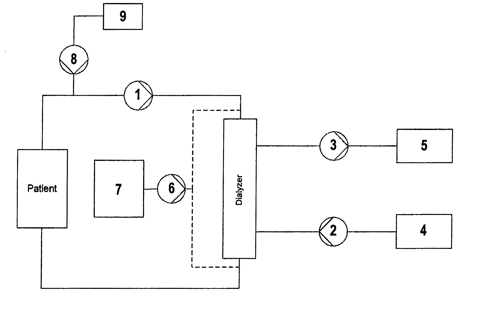
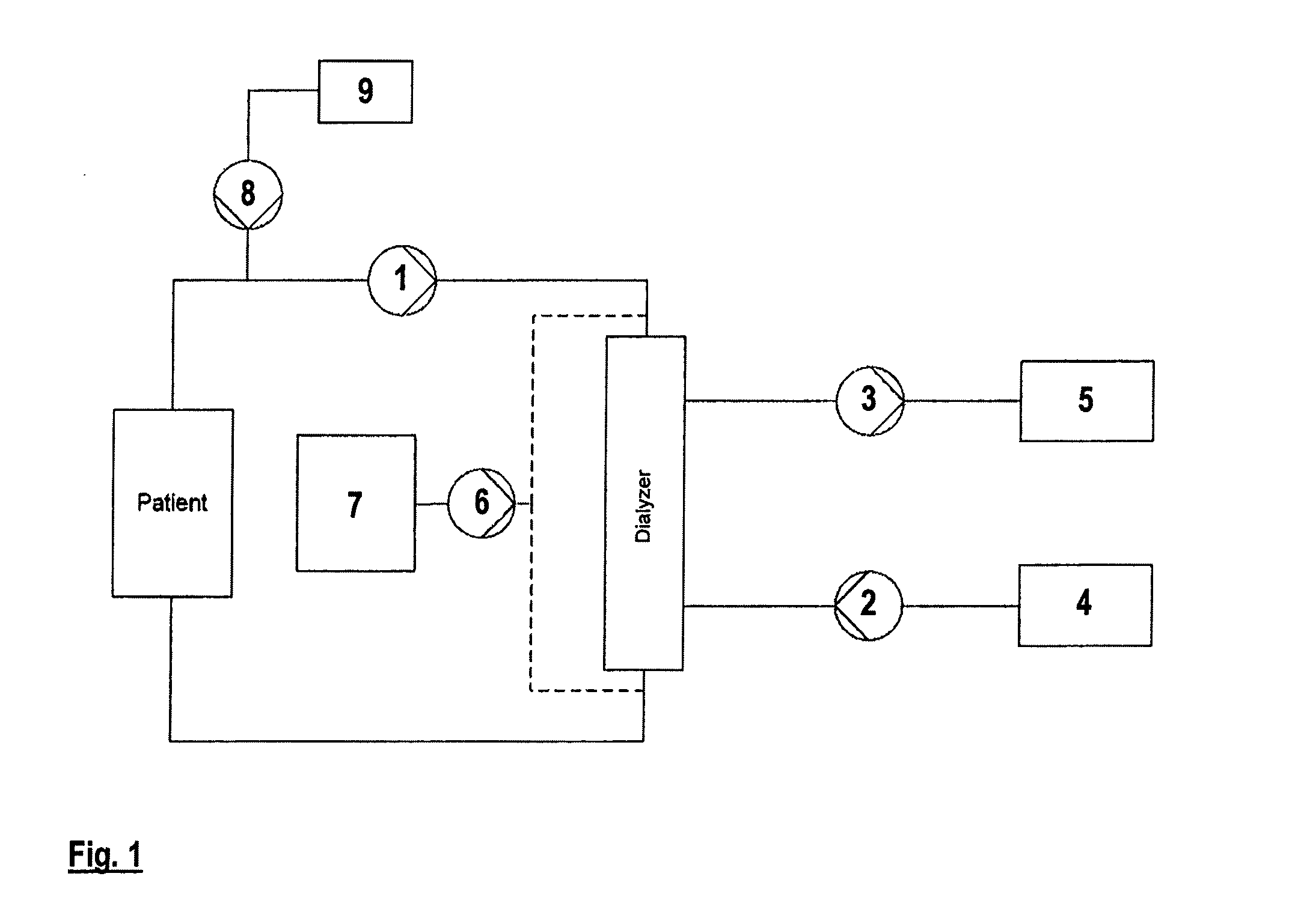
[0015]FIG. 1 shows a schematic of an embodiment of a dialysis system of the present invention, suitable for use in intense care. A piezo pump (1) is provided for pumping the patient's blood through the extracorporeal cicuit. Piezo pumps (2,3) are provided for pumping dialysate from a source of dialysate (4), e.g., a bag or a device for on-line preparation of dialysate, thr...


PUM


Abstract

The present invention relates to dialysis devices comprising peristaltic pumps of linear build with piezoelectric actuators.

Description

FIELD OF THE INVENTION[0001]The present invention relates to dialysis devices comprising peristaltic pumps of linear build with piezoelectric actuators.BACKGROUND OF THE INVENTION[0002]In present-day dialysis systems, liquid transport is normally carried out by radial peristaltic pumps which are employed to pump blood, dialysis liquid or liquids or concentrates used for its preparation, and filtrate.[0003]Disadvantages of the radial peristaltic pumps used up to now are their installation size and weight, which contribute to the considerable space requirement and weight of conventional dialysis systems, causing these systems to often be very bulky and heavy and cumbersome to transport. In addition to that, this type of pumps produces an unpleasant noise level during operation and shows high power consumption and heat generation associated with it.[0004]It would therefore be desirable, especially also in view of the development of systems for home dialysis or the development of portab...

Claims


Application Information

Patent Timeline
IPC IPC(8): A61M1/14A61M1/28A61M60/113A61M60/284A61M60/37A61M60/454
CPCA61M1/1053A61M1/16A61M1/28A61M1/1058F04B43/095F04B43/12A61M1/1041F04B43/021A61M1/1696A61M1/1605A61M2205/0283F04B43/14A61M60/113A61M60/284A61M60/37A61M60/454
Inventor WAGNER, STEFFANFLIEG, RALF
Owner GAMBRO LUNDIA AB
Why Eureka
Try Eureka