
Tool for minimally invasive surgery

a technology for surgery and tools, applied in the field of easy-to-control tools for minimally invasive surgery, can solve the problems of difficult surgery dexterous handling, huge installation and maintenance costs, and high equipment costs of robotic surgical systems, and achieves the effects of minimal invasiveness, convenient movement, and small volum

Active Publication Date: 2011-05-05
JEONG CHANG WOOK
View PDF10 Cites 44 Cited by
  • Summary
  • Abstract
  • Description
  • Claims
  • Application Information

AI Technical Summary

Benefits of technology

[0010]Another object of the present invention is to provide a tool for minimally invasive surgery, which a user can freely actuate without the help of a special drive element.
[0011]A further object of the present invention is to provide a tool for minimally invasive surgery, which features small volume, lightweight, and convenient movability.

Problems solved by technology

Particularly, since the traditional end effector has no bending portion like a joint, it is difficult to perform a dexterous handling required for surgery.
However, this robotic surgical system is very expensive equipment, and moreover, it costs a tremendous amount of money to install and maintain after installation.
This equipment is also bulky and very heavy (even the robotic cart alone is about 2 m tall and as heavy as 544 kg).
Needless to say, it is difficult to move the equipment around, so the surgery has to be performed only in a place where the system is already installed.
Besides, in case of using the robotic system, surgeons feel lack of tactile sense, as compared with using the traditional tools for laparoscopic surgery.

Method used


Image

  • Tool for minimally invasive surgery
  • Tool for minimally invasive surgery
  • Tool for minimally invasive surgery

Examples


Embodiment Construction

[0023]In the following detailed description, reference is made to the accompanying drawings that show, by way of illustration, specific embodiments in which the invention may be practiced. These embodiments are described in sufficient detail to enable those skilled in the art to practice the invention. It is to be understood that the various embodiments of the invention, although different, are not necessarily mutually exclusive. The following detailed description is, therefore, not to be taken in a limiting sense, and the scope of the present invention is defined only by the appended claims that should be appropriately interpreted along with the full range of equivalents to which the claims are entitled.

[0024]Hereinafter, preferred embodiments of the present invention will be explained in detail with reference to the accompanying drawing.

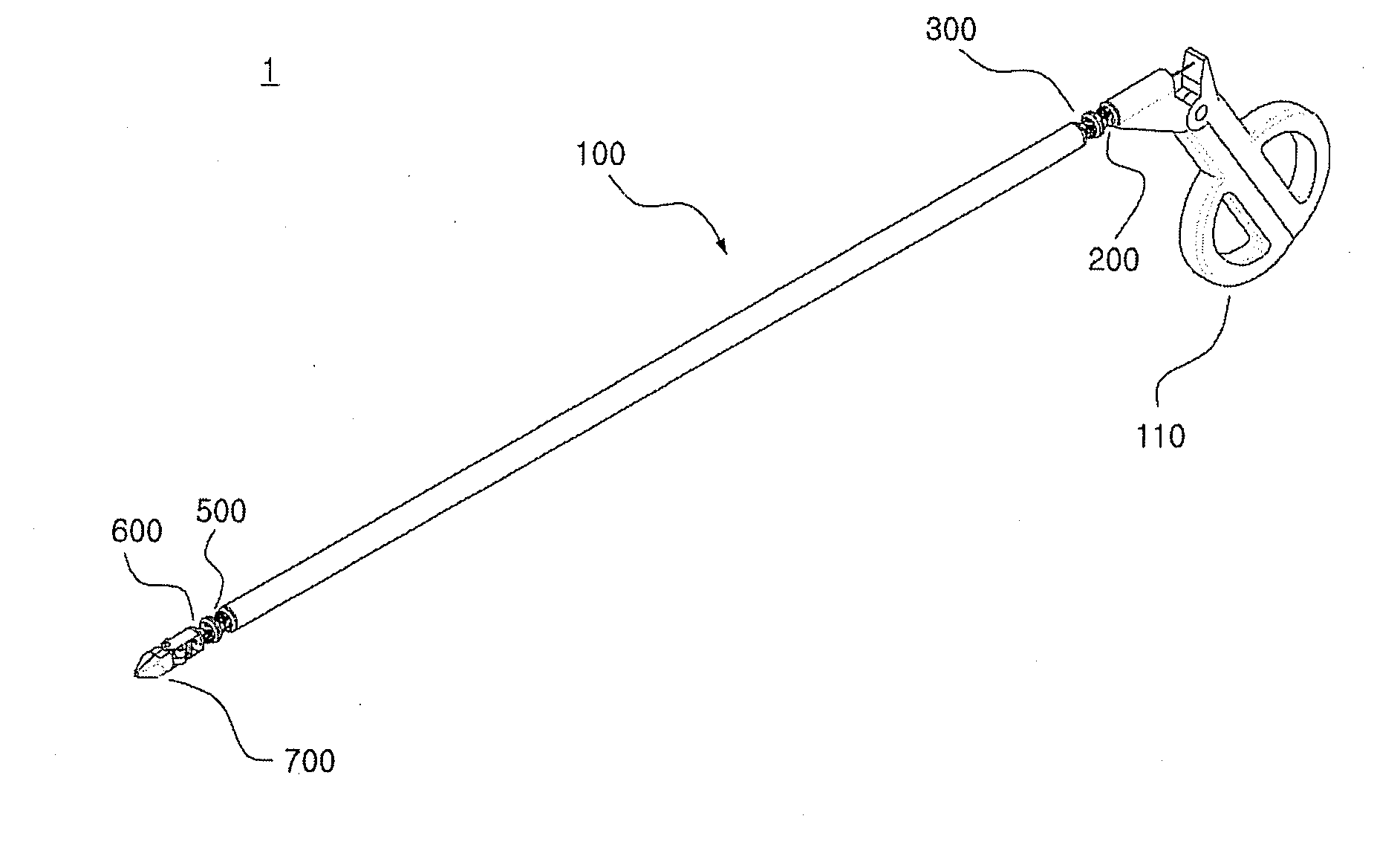
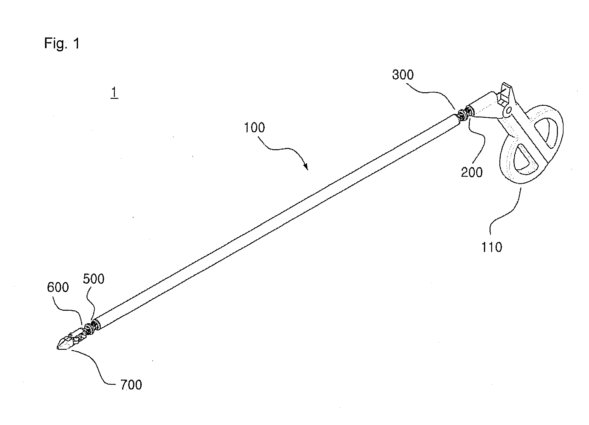
[0025]FIG. 1 is a perspective view showing the outer appearance of a tool 1 for minimally invasive surgery, in accordance with one embodiment of t...


PUM


Abstract

The present invention relates to an easy-to-control tool for minimally invasive surgery. In accordance with an aspect of the present invention, there is provided a tool for minimally invasive surgery comprising, an elongated shaft having a predetermined length, an adjustment handle manually controllable by a user, a pitch direction handling part and a yaw direction handling part positioned around one end of the elongated shaft for transferring motions in pitch and yaw directions following the actuation of the adjustment handle, a pitch direction actuating part and a yaw direction actuating part positioned around the other end of the elongated shaft for operating corresponding to the operations from the pitch direction handling part and the yaw direction handling part, respectively, an end effector controllable by the pitch direction actuating part and the yaw direction actuating part, and a plurality of cables for transferring the from the pitch direction handling part and the yaw direction handling part to the pitch direction actuating part and the yaw direction actuating part, respectively.

Description

FIELD OF THE INVENTION[0001]The present invention relates to an easy-to-control tool for minimally invasive surgery, and more specifically, to a tool, which includes an adjustment handle connected to one end of a predetermined shaft and an end effector that is connected to the other end of the shaft and controllable merely through the actuation of the adjustment handle, so as to perform minimally invasive surgery.BACKGROUND OF THE INVENTION[0002]Minimally invasive surgery is a surgical approach that involves use of instruments inserted through several tiny incision openings to perform a surgery causing minimal tissue trauma.[0003]This minimally invasive surgery relatively reduces changes in metabolism of the patient in the period of post-surgical care, so it is beneficial to rapid recovery of the patient. Therefore, using such minimally invasive surgery shortens length of a hospital stay of the patient after the surgery and allows patients to return to normal physical activities mor...

Claims


Application Information

Patent Timeline
IPC IPC(8): A61B17/29
CPCA61B17/29A61B2017/003A61B2017/291A61B2017/2927Y10T74/184A61B19/22A61B2017/2941A61B2019/2242Y10T74/20238A61B2019/2238A61B34/70A61B34/71A61B2034/306A61B17/28A61B17/32
Inventor JEONG, CHANG WOOK
Owner JEONG CHANG WOOK
Learn More