Low visibility landing system

a low-visibility, landing system technology, applied in the direction of process and machine control, vehicle position/course/altitude control, instruments, etc., to achieve the effect of greater accuracy

Inactive Publication Date: 2011-05-05
GULFSTREAM AEROSPACE CORP
View PDF11 Cites 43 Cited by
  • Summary
  • Abstract
  • Description
  • Claims
  • Application Information

AI Technical Summary

Benefits of technology

[0011]In one embodiment of the invention, a low visibility landing system may integrate a first signal from a first landing system and a second signal from a second landing system to generate a hybrid signal that has a greater accuracy than the first signal or second signal individually. For example, a hybrid signal may be generated from an ILS signal and a WAAS signal. In some cases, the use of a hybrid signal may allow an aircraft to lower the DH and the RVR, which would provide pilots the ability to descend further before having to abort a landing in poor visibility conditions. The hybrid signal may provide deviation and guidance data to the aircraft so that the pilot or autopilot will be able to properly position the aircraft along an approach path during landing. As in a conventional landing system employing only ILS or only WAAS, for example, if the deviation of the aircraft from the landing approach exceeds a certain threshold, then the pilot may be need to abort the landing approach.

Problems solved by technology

For example, if the difference between the first signal and the second signal becomes too large, exceeding a threshold, then the system may alert the pilot to a possible failure or automatically require the pilot to abort the landing and try again.

Method used


Image

  • Low visibility landing system
  • Low visibility landing system
  • Low visibility landing system

Examples


Embodiment Construction

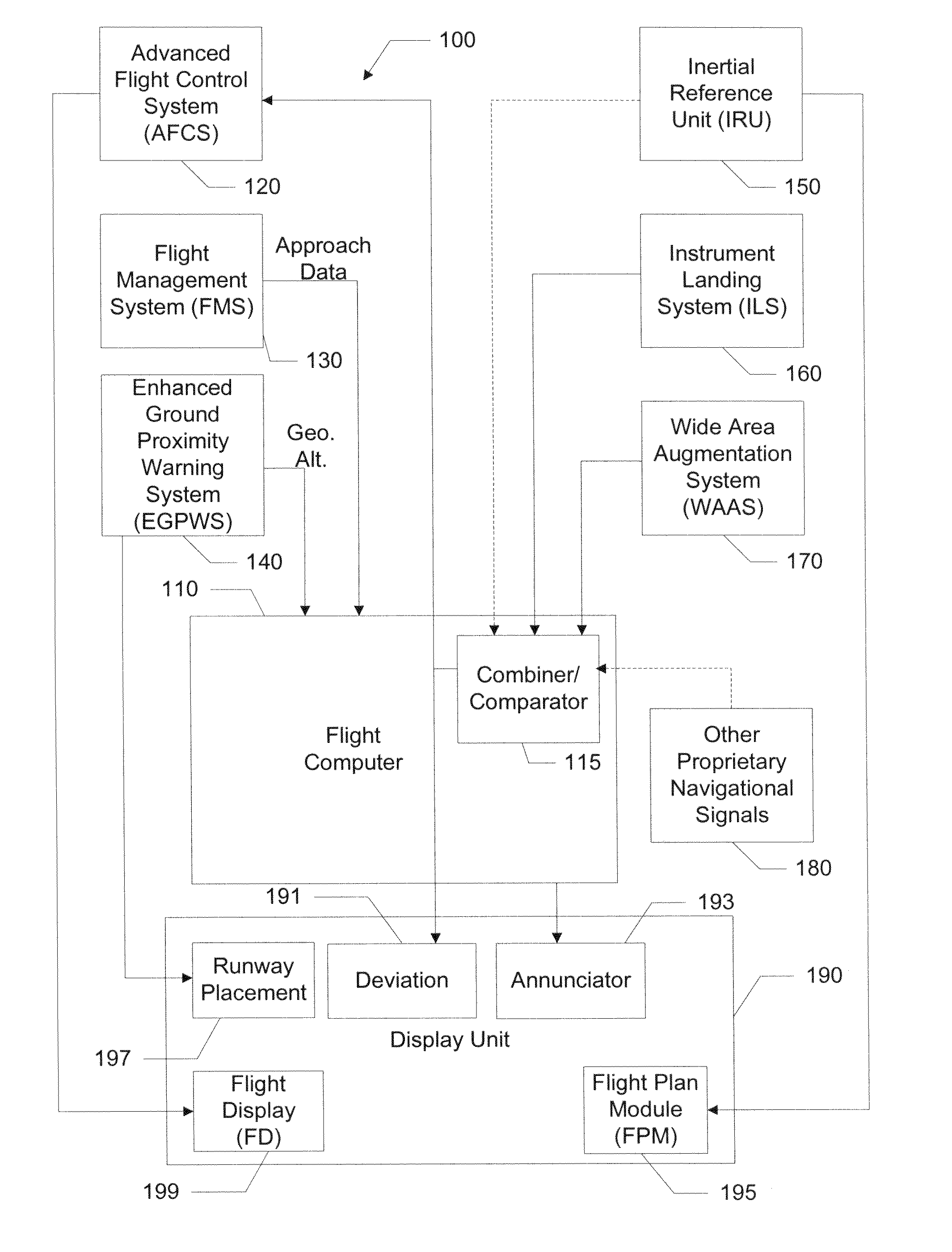
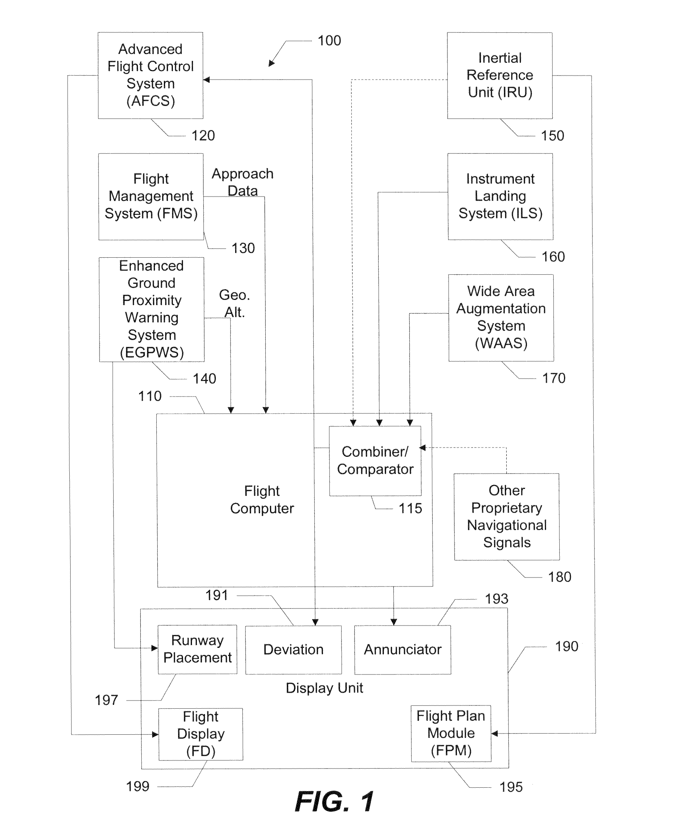
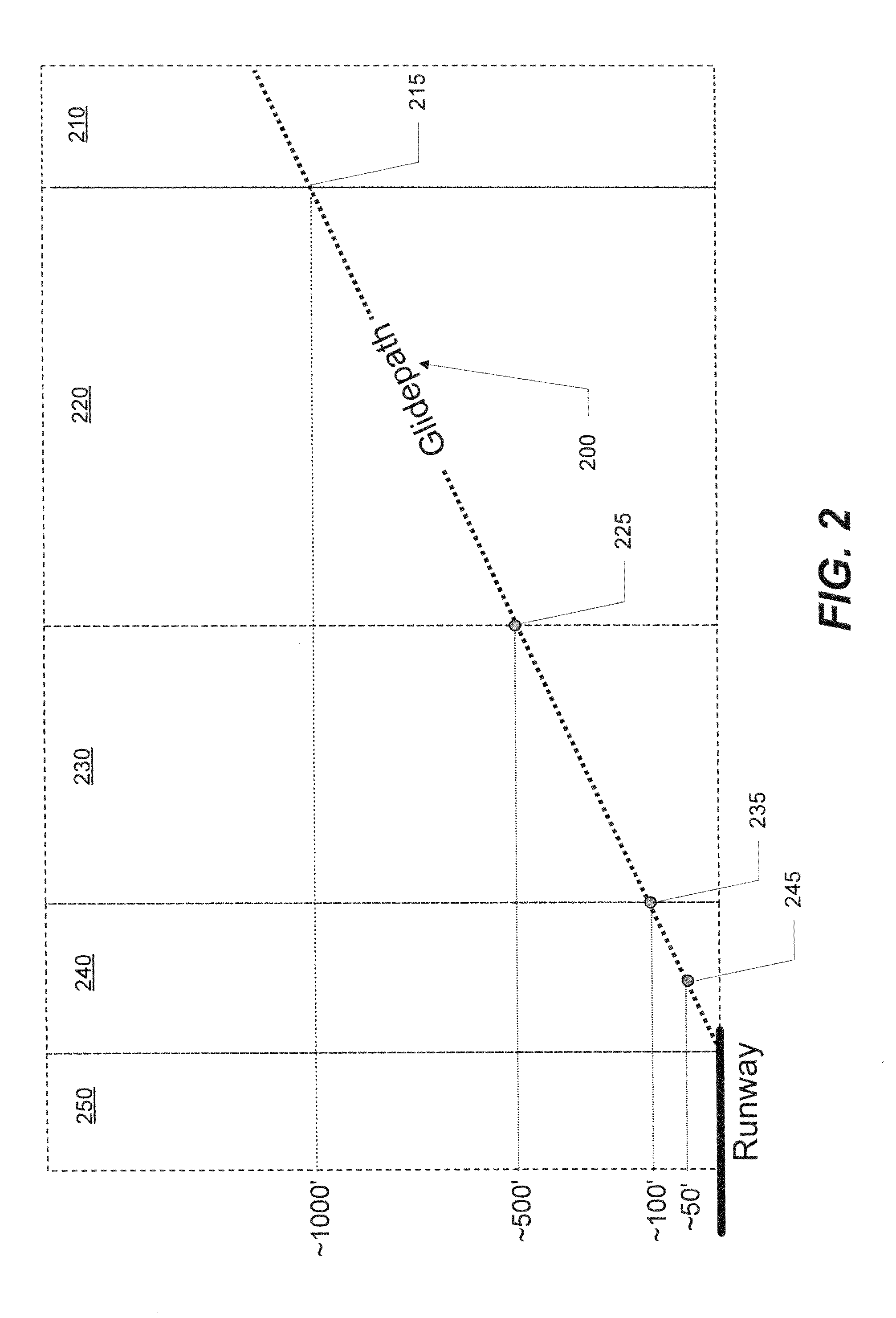
[0025]CAT I, CAT II, and CAT III landing approaches use high precision landing systems that may employ different ground, satellite, and aircraft based equipment to aid in landing the aircraft. In at least one embodiment of the invention, a low visibility landing system may be configured such that aircraft landing approaches may proceed to lower altitudes for a decision height (DH) and to a closer distance for before the runway visual range (RVR). In some cases, embodiments of the present invention may utilize equipment configured for CAT I landings and use the equipment to execute a landing procedure with lower DH and RVR than would be possible under conventional CAT I landing procedures.

[0026]In one embodiment of the invention, a low visibility landing system may be configured to generate a hybrid signal from the separate signals of two landing systems. For example, the landing system may use the signals from an Instrument Landing System (ILS) and a Wide Area Augmentation System (W...


PUM


Abstract

Examples of the present invention may include a low visibility landing system for guiding aircraft on landing approaches. The low visibility landing system may aid a pilot during landing in low visibility conditions such that an aircraft may descend to lower altitudes without visual contact with the runway than is possible with other landing systems. The system may use various navigational systems to produce a hybrid signal that may be more stable than individual signals of those navigational systems. The hybrid signal is compared to a predetermined landing approach plan to determine the deviation of the aircraft from the landing approach plan and to provide guidance to the pilot to get the aircraft back onto the landing approach plan. The system may also use multiple navigational systems to perform checks on an operation of a primary navigational system to ensure that the primary navigational system is operating accurately.

Description

FIELD OF THE INVENTION[0001]Embodiments of the present invention relate to aircraft landing systems and, more particularly, to landing systems used in low visibility conditions.BACKGROUND OF THE INVENTION[0002]Currently, commercial aircraft employ guidance systems that warn pilots when the aircraft is deviating from a flight path. Guidance systems must have certain levels of accuracy, integrity, continuity, and availability during ordinary flight. Guidance systems that are used for landing require additional levels of accuracy, integrity, continuity, and availability. Landing systems typically provide high precision data relating to position and deviation of an aircraft from a landing approach path. This high precision often requires special equipment, which can be beneficial in situations where fog, clouds, and / or other conditions reduce visibility.[0003]Airport landing systems are categorized by the Federal Aviation Administration (FAA) or other certification authority into differ...

Claims


Application Information

Patent Timeline
Patent Type & Authority Applications(United States)
IPC IPC(8): G05D1/00G06F19/00G05D1/10
CPCG05D1/0676G08G5/025G08G5/0021
Inventor TAKACS, ROBERT S.FREEMAN, GARY M.
Owner GULFSTREAM AEROSPACE CORP
Why Eureka
Try Eureka