Holding mechanism for electrical connectors and pcbs

a technology of holding mechanism and electrical connector, which is applied in the direction of manufacturing tools, coupling device connections, metal working apparatuses, etc., can solve the problems of affecting the performance of electronic connectors, consuming electrical connector assembling, and delay in subsequent assembly, so as to reduce the difficulty of soldering, improve the quality of soldering, and improve the effect of soldering efficiency

Inactive Publication Date: 2011-05-12
CHENG UEI PRECISION IND CO LTD
View PDF19 Cites 4 Cited by
  • Summary
  • Abstract
  • Description
  • Claims
  • Application Information

AI Technical Summary

Benefits of technology

[0007]As described above, the holding component provides the receiving chamber for receiving the plural electrical connectors and the corresponding PCBs. The stopping plate is capable of moving with respect to the holding component and fixing the electrical connectors from the frontward direction. The locking component is capable of moving with respect to the holding component and fixing the PCBs from the rearward direction and the up direction. Thus the electrical connectors and the PCBs are fixed firmly, which addresses the problem that the operator manually fixes the electrical connector and the PCB in soldering process, thereby reducing the solder difficulty and improving the solder quality. Meanwhile, the holding mechanism is capable of fixing the plural electrical connectors and the PCBs at one time, which is excellent to raise the solder efficiency.

Problems solved by technology

But, since the electrical connector is complicated and small, it is difficult and time-consuming to assemble the electrical connector, especially, some processes are important and require precise operation, for preventing from affecting quality of the electrical connector, such as soldering terminals to a printed circuit board (PCB).
If there is any careless, there result in the soldering failure between the electrical connector 80 and the PCB 90, which not only affects the performance of the electronic connector 80, but also delays the subsequent assembling process.

Method used


Image

  • Holding mechanism for electrical connectors and pcbs
  • Holding mechanism for electrical connectors and pcbs
  • Holding mechanism for electrical connectors and pcbs

Examples


Embodiment Construction

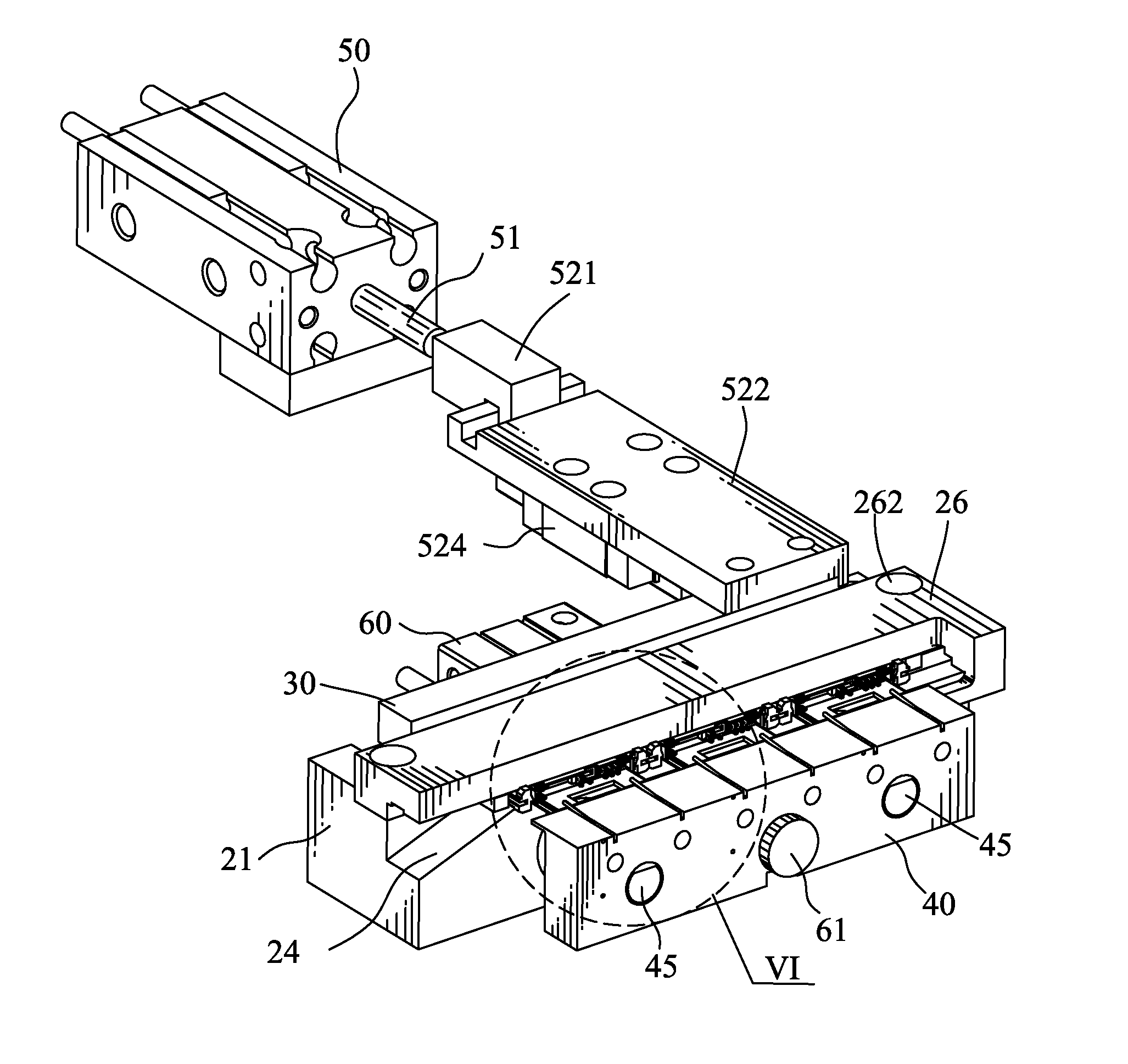
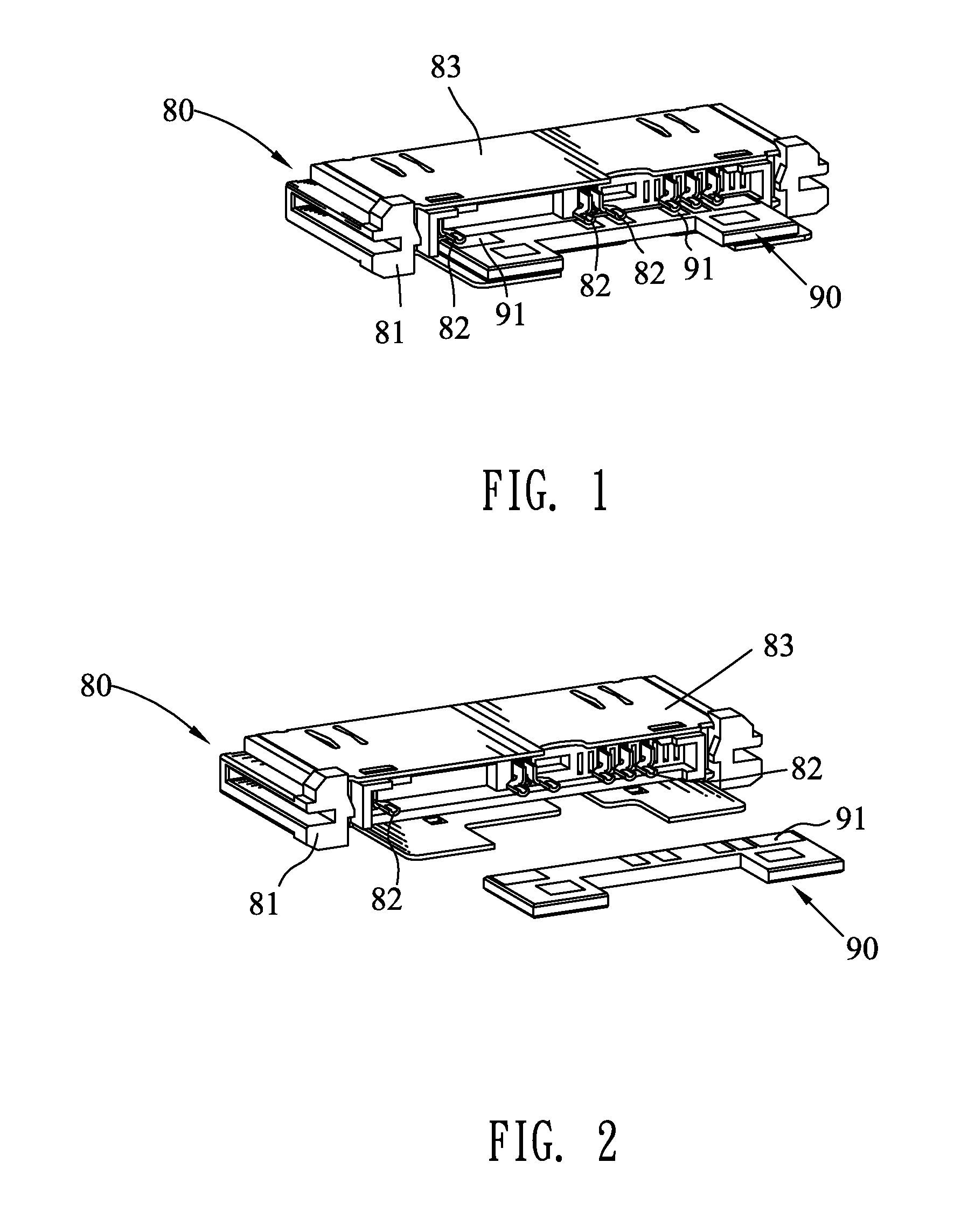
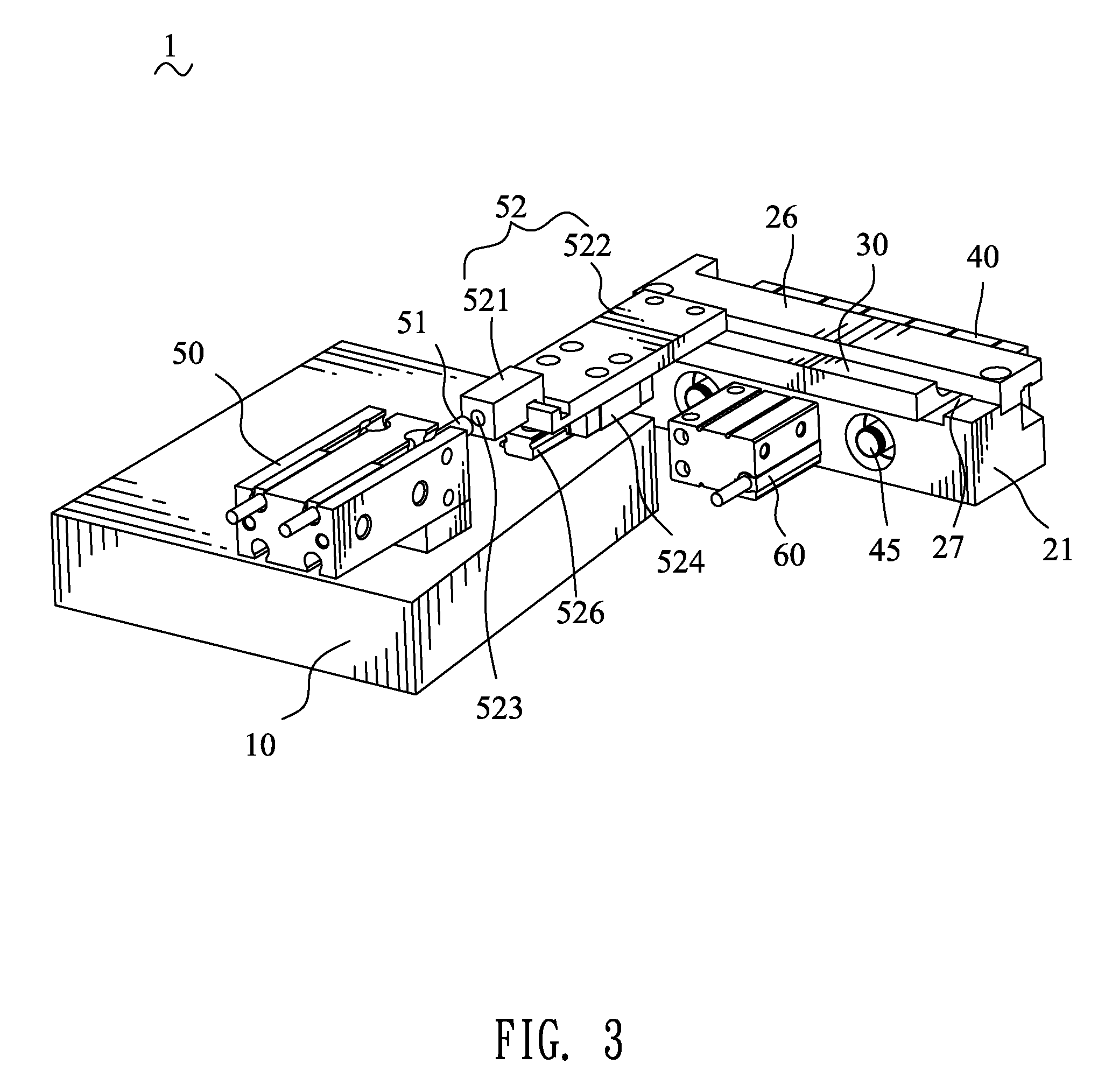
[0017]Referring to the drawings in greater detail, and first to FIGS. 3-4, the embodiment of the invention is embodied in a holding mechanism 1 which is adapted for holding a plurality of small electronic devices, such as electrical connectors, for facilitating the operation, such as solder. Hereafter, the holding mechanism 1 of this embodiment is described in detail, cooperating with the electrical connector 80 and the PCB 90 in prior art, but should not be limited.

[0018]The holding mechanism 1 comprises a supporting platform 10, a holding component 20 disposed rearward of the supporting platform 10, a stopping plate 30, a locking component 40, a first driving component 50 and a second driving component 60. The first and second driving components 50, 60 are respectively mounted to the supporting platform 10 and the holding component 20, functioned as drive. The stopping plate 30 is connected with the first driving component 50 and urged to move frontward and rearward with respect t...


PUM

PropertyMeasurementUnit
areasaaaaaaaaaa
timeaaaaaaaaaa
distanceaaaaaaaaaa

Abstract

A holding mechanism has a holding component including a base and a covering plate. The covering plate has two supporting pegs at two ends of a bottom thereof fixed on a top surface of the base, for forming a receiving chamber where a plurality of electrical connectors, with PCBs inserted therein, is arranged side by side. A stopping plate is capable of being driven to insert into and withdraw from the receiving chamber from a frontward direction, for resting front ends of the electrical connectors. A locking component is capable of moving frontward and rearward, and has a main body disposed rearward of the base. The main body has an upper portion protruded frontward to form a locking portion, for resting rear ends of the PCBs, and a plurality of pressing elements extending frontward above and beyond the locking portion, for pressing exposed top surfaces of the inserted PCBs.

Description

BACKGROUND OF THE INVENTION[0001]1. Field of the Invention[0002]The present invention relates to a holding mechanism, and particularly to a holding mechanism which is capable of fixing a plurality of electrical connectors and printed circuit boards (PCBs).[0003]2. The Related Art[0004]With the ever-increasing development of electronic technology, various electronic devices come into exist in daily life and are constantly renewed toward multifunction and miniaturization for meeting the demands of the users. Consequently, electrical connectors, with compact and small configurations, serving as transitional connection devices, are widely used. But, since the electrical connector is complicated and small, it is difficult and time-consuming to assemble the electrical connector, especially, some processes are important and require precise operation, for preventing from affecting quality of the electrical connector, such as soldering terminals to a printed circuit board (PCB).[0005]FIG. 1 ...

Claims


Application Information

Patent Timeline
Patent Type & Authority Applications(United States)
IPC IPC(8): H05K13/00B23P19/00
CPCH01R12/72Y10T29/53265H01R43/0256
Inventor CHEN, SUNG-LINWU, XIAO-LINZHANG, SHAOBOZOU, ZAI-WEIMA, JUN
Owner CHENG UEI PRECISION IND CO LTD
Why Eureka
Try Eureka