Heat Dissipating device

Inactive Publication Date: 2011-05-12
SUNONWEALTH ELECTRIC MACHINE IND
View PDF19 Cites 40 Cited by
  • Summary
  • Abstract
  • Description
  • Claims
  • Application Information

AI Technical Summary

Benefits of technology

[0006]An objective of the present invention is to provide a heat dissipating device that can operate

Problems solved by technology

However, moisture, dust, etc. contained in the ambient air enters the compartment 71 together with the air,

Method used


Image

  • Heat Dissipating device
  • Heat Dissipating device
  • Heat Dissipating device

Examples


Embodiment Construction

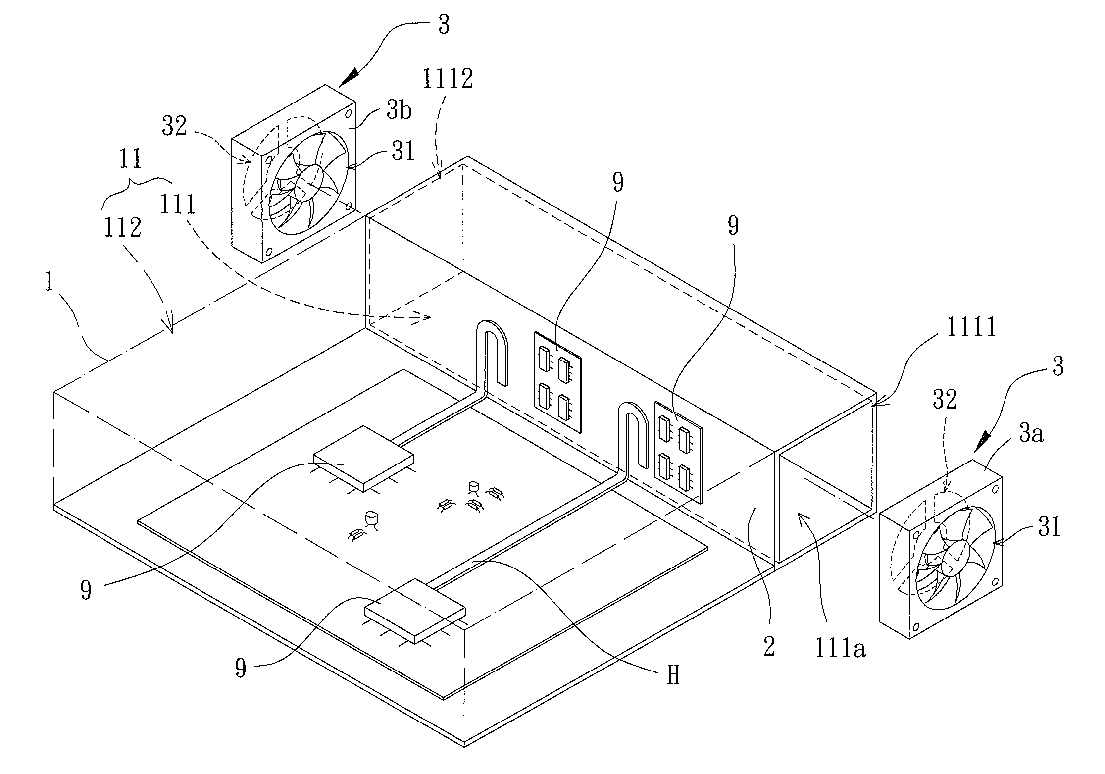
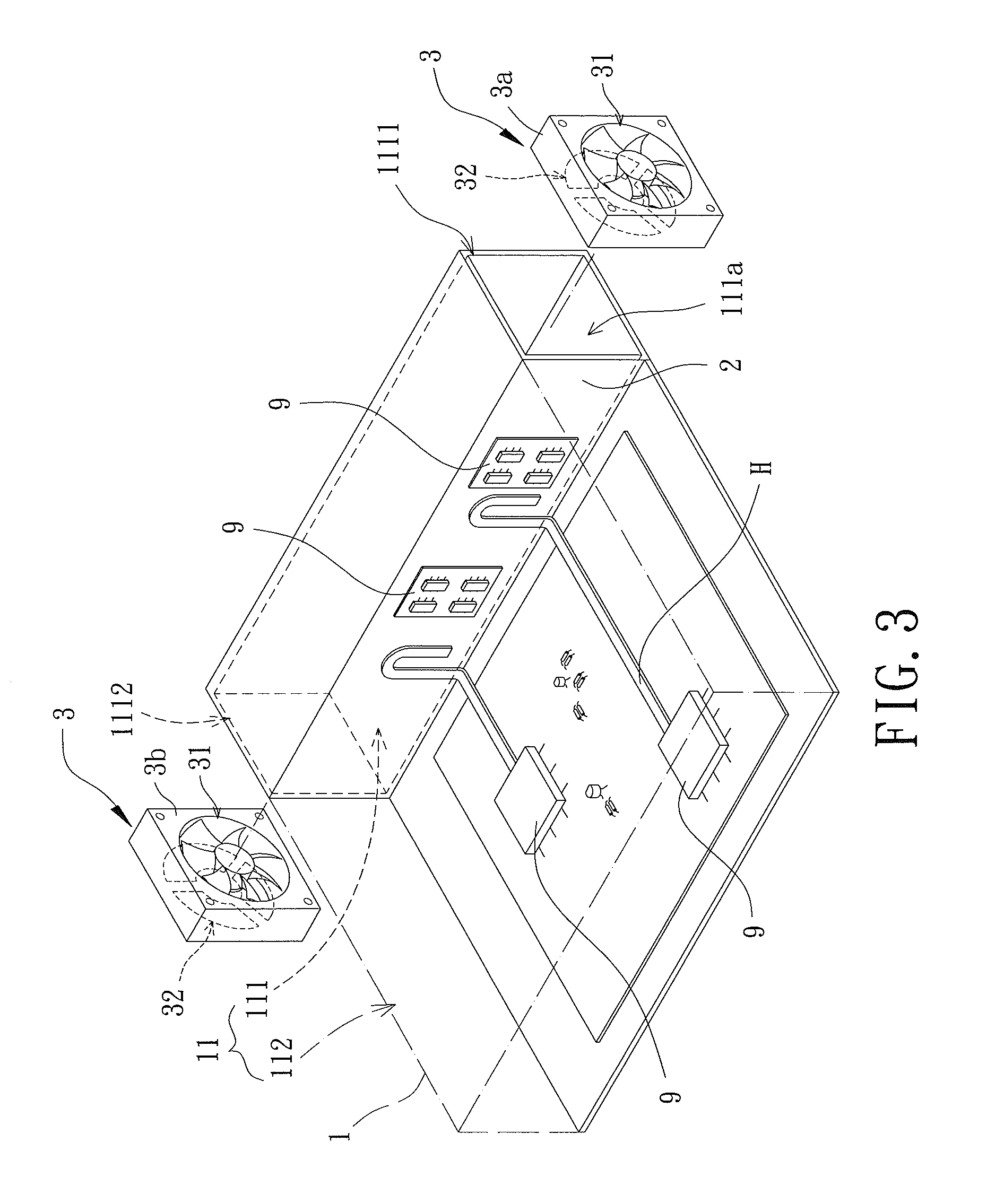
[0025]A heat dissipating device of a first embodiment according to the preferred teachings of the present invention is shown in FIGS. 3-5. The heat dissipating device is utilized to dissipate heat generated by a plurality of electronic elements 9 mounted in a casing of an electronic product such as a camera, electronic digital displayer, notebook, satellite navigation device, etc. The heat dissipating device includes a casing 1, at least one heat conducting board 2, and at least one fan unit 3. The casing 1 includes a compartment 11. The at least one heat conducting board 2 is integrally formed or detachably mounted in the compartment 11, dividing the compartment 11 into a first chamber receiving the at least one fan unit 3 and a second chamber receiving the electronic elements 9 such as circuit boards, microprocessors, chips, etc. The at least one heat conducting board 2 is made of metal with excellent heat conduction characteristics, such as aluminum, copper, gold, silver, or an a...


PUM


Abstract

A heat dissipating device includes a casing having a compartment. At least one heat conducting board is mounted in the compartment and divides the compartment into first and second chambers. The first chamber includes a plurality of openings. At least one fan unit is mounted in the first chamber and includes at least one air inlet and at least one air outlet. The air inlet is in communication with a first one of the plurality of openings. The air outlet is in communication with a second one of the plurality of openings. By utilizing the heat conducting board to absorb the heat generated by electronic elements in the second chamber and by creating airflow in the first chamber with the fan unit, the temperature of the second chamber and the electronic elements is lowered while preventing moisture or dust from entering the first chamber.

Description

BACKGROUND OF THE INVENTION[0001]1. Field of the Invention[0002]The present invention relates to a heat dissipating device and, more particularly, to a heat dissipating device that can operate without adverse affect by moisture, dust, etc.[0003]2. Description of the Related Art[0004]Electronic elements, such as microprocessors, chips, etc., of most electronic products are generally concentrated and mounted in a casing. However, the temperature in a generally sealed inner chamber of the casing rises more rapidly as the functions and operating speed of the electronic elements upgrade. Heat dissipating devices, such as fans or heat sinks, are provided to dissipate heat to maintain normal operation of the electronic elements at an appropriate temperature and to prolong the service lives of the electronic elements.[0005]FIGS. 1 and 2 show a conventional heat dissipating device including a casing 7 and two fan units 8. Specifically, the casing 7 includes a compartment 71 receiving a plura...

Claims


Application Information

Patent Timeline
IPC IPC(8): F28D21/00
CPCF28D15/0233F28D2021/0029G06F1/28H01L23/427H05K7/20163H01L2924/0002H05K7/20154H01L2924/00
Inventor HORNG, ALEXYIN, TSO-KUO
Owner SUNONWEALTH ELECTRIC MACHINE IND
Why Eureka
Try Eureka