
System for Spot Welding with a Laser Beam

a laser beam and laser beam technology, applied in laser beam welding equipment, welding equipment, manufacturing tools, etc., can solve the problems of unnecessarily high degree of technical complexity and cannot be automatically used for other combinations of components, and achieve the effect of easy production

Active Publication Date: 2011-05-12
JENOPTIK AUTOMATISIERUNGSTECHN
View PDF12 Cites 12 Cited by
  • Summary
  • Abstract
  • Description
  • Claims
  • Application Information

AI Technical Summary

Benefits of technology

[0015]The problem to be solved by the present invention is to make available a system for spot welding with a laser beam, which system can be easily produced and flexibly adapted to a variety of applications by variably adjusting the contact force and changing the size and shape of the weld spots with only minimal changes to the system.
[0019]Compared to a system that comprises only one welding unit, and by means of which, consistent with the individual weld spots, only one weld spot after the other can be produced, a system that comprises as few as, e.g., two or three welding units that are disposed along a straight line offers an advantage. Using this type of system, it is possible to produce groups of weld spots one group at a time, or, if several systems are simultaneously used, groups of weld spots at the same time. Thus, a system of this type makes it possible to produce a great variety of patterns of weld spots; however, it does not allow the spacing between the weld spots to be varied, while this is invariably possible with a system with only one welding unit.
[0021]A special advantage is that, through the selection of the size and shape of the cross section of the tube, it is possible to predetermine the size and shape of the weld spots. In many cases, it is more suitable for a weld spot to have a rectangular shape instead of the normally round shape. Irrespective of its cross-sectional shape and size, such a tube can be inexpensively produced. The tube should be long enough to ensure that excellent homogenization can take place as a result of the large number of reflections, which leads to a uniformly strong weld joint within the weld spot.
[0022]To be able to design the contact surface, by means of which the end of the tube is pressed against the components that are to be welded together, regardless of the tubular cross section used, a pressure member can be conveniently attached to the free end of the tube.
[0026]Using a flat plate which is made of a material transparent to the laser beam and which seals the end of the tube, the components to be welded together are in contact with each other across the entire surface of the weld spot, which can be an advantage especially when sheeting materials are welded together.

Problems solved by technology

Opening and closing a laser trap by mounting and removing the system and the associated actuation of a switch to doubly ensure that laser radiation is unable to escape from the system in case the system was not mounted properly as a means for automatically guiding and operating the system demands an unnecessarily high degree of technical complexity.
Another disadvantage of the device disclosed by DE 100 05 593 is that the contact force of the system is predetermined by the dimension of the compression spring, which means that the unit is optimized for a specific combination of components and can therefore not be automatically used for other combinations of components, in other words, components made of different materials or with different dimensions, in particular different material thicknesses in the welding area.
In addition, the size of the weld spots is also predetermined by the beam-forming optical system and cannot be changed.

Method used


Image

  • System for Spot Welding with a Laser Beam
  • System for Spot Welding with a Laser Beam
  • System for Spot Welding with a Laser Beam

Examples


Embodiment Construction

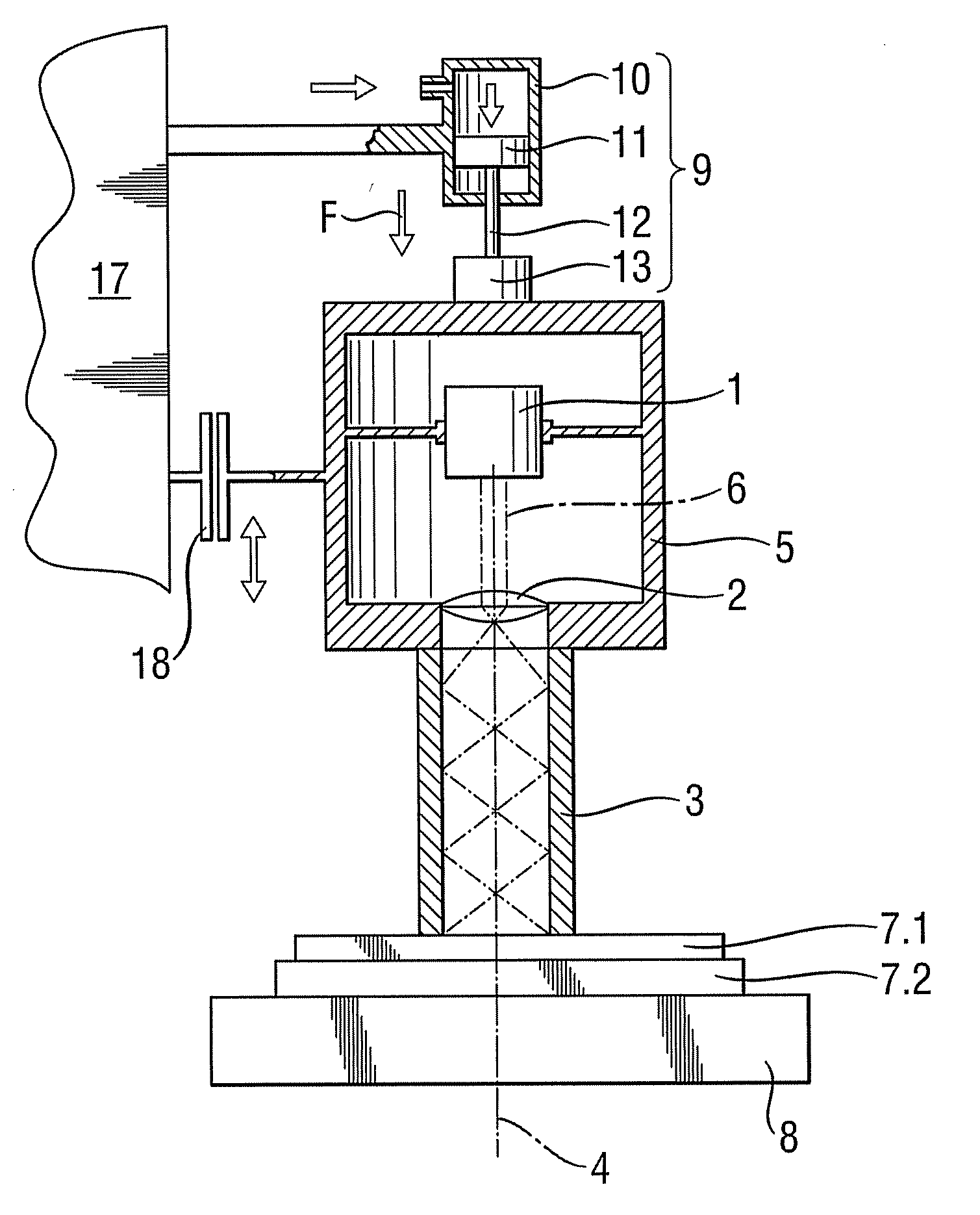
[0039]FIG. 1 shows a first practical example of a system for spot welding with a laser beam.

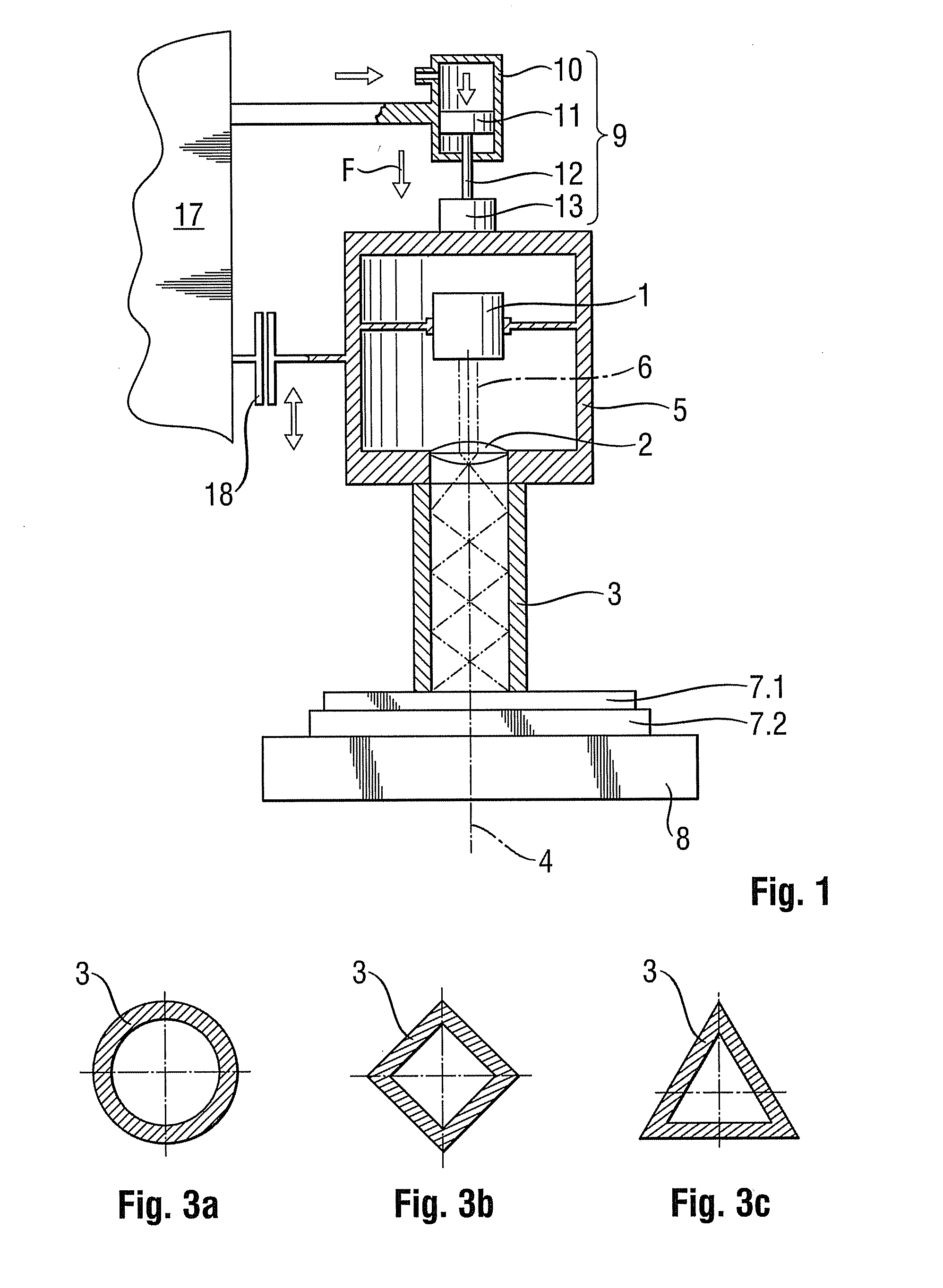
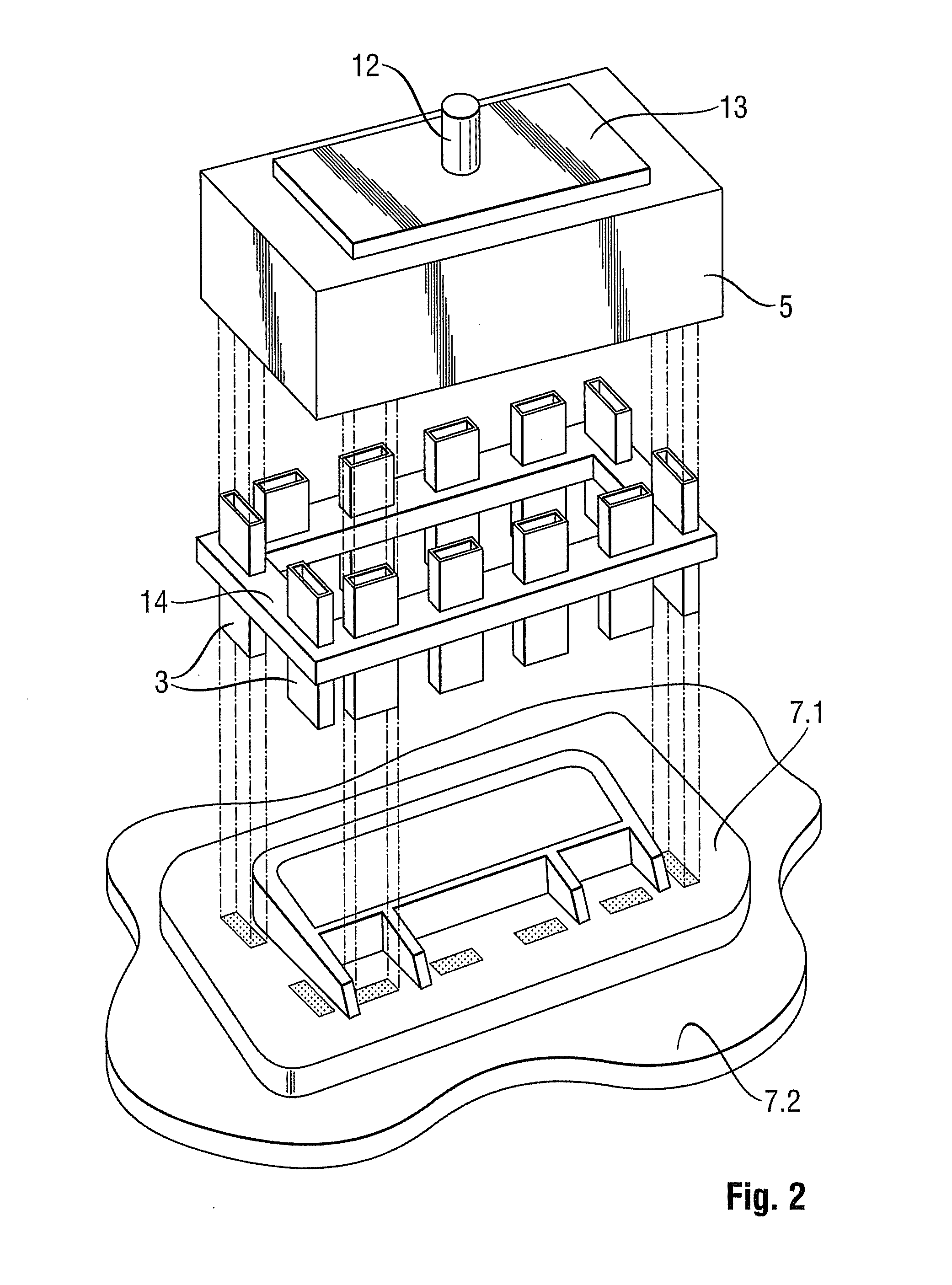
[0040]The system essentially comprises a high-power diode laser 1 which emits a laser beam 6, a beam-forming optical system 2 which, in the direction of the beam, is disposed downstream thereof and a tube 3, which together are disposed on an optical axis 4 and which are rigidly connected to each other via a housing 5.

[0041]It is useful if the high-power diode laser 1 is a laser diode bar that comprises a plurality of individual laser diodes, which, overall, form an emitting line measuring, e.g., 1×10 mm, which are preceded upstream by a collimating optical system.

[0042]The pre-collimated laser beam 6 is expanded by means of the downstream beam-forming optical system 2 to ensure that it is completely coupled into the tube 3 and has an angle of divergence that leads to multiple reflections as the laser beam passes through the tube. To minimize the radiation losses, multiple reflections should t...


PUM

PropertyMeasurementUnit
Forceaaaaaaaaaa
Pressureaaaaaaaaaa
Sizeaaaaaaaaaa

Abstract

The present invention relates to a system for spot welding with a laser beam (6) in which the laser beam (6) passes through a tube (3) and impinges on the components (7.1, 7.2) to be welded together. The cross section of the laser beam (6) is formed by reflections inside the tube, and the distribution of the radiation intensity is homogenized across the cross section of the beam. At the same time, the tube (3) exerts a contact force (F) on the components (7.1, 7.2) that are to be welded together. Using a plurality of laser beams (6), to each of which a tube (3) is dedicated downstream, it is possible to create a simple and robust, component-specific system by means of which several or all weld spots can be simultaneously produced so as to conjoin the two components (7.1, 7.2).

Description

FIELD OF THE INVENTION[0001]The present invention relates to a method [sic] for spot welding with a laser beam as it is generically known from DE 100 05 593 C1.[0002]Regardless of the composition of the material of the two components that are to be welded together, the objective of spot welding is to permanently conjoin the two components via a predetermined number, location, shape and size of weld spots. In many applications, in particular if spot welding involves laser transmission welding of plastic materials, an additional objective is that the weld spots should not be visible on the laser-absorbent surface of the component.[0003]Thus, in addition to the standard requirements to be met by tool assemblies, such as low maintenance, light weight, and material- and cost-efficiency, an industrially feasible system for spot welding should also meet the requirement of a uniform distribution of the laser energy, in the weld spot.[0004]It is obvious to the person skilled in the art that ...

Claims


Application Information

Patent Timeline
IPC IPC(8): B23K26/00
CPCB23K26/023B29C66/8322B23K26/22B29C65/1635B29C65/1667B29C65/1674B29C65/1687B29C66/112B29C66/131B29C66/21B29C66/47B29C66/474B29C66/8242B29C66/8266B23K26/0732B23K26/037B29C66/1122
Inventor WOLLMANN, WERNERKRAEMER, WILFRIEDLANGEBACH, JANFISCHBACH, SVEN
Owner JENOPTIK AUTOMATISIERUNGSTECHN
Learn More