
Power Oscillation Damping Employing a Full or Partial Conversion Wind Turbine

a wind turbine and full or partial conversion technology, applied in the control of electric generators, machines/engines, mechanical equipment, etc., can solve the problems of transmission lines generating reactive power, consuming reactive power, and consuming reactive power

Active Publication Date: 2011-05-12
SIEMENS GAMESA RENEWABLE ENERGY AS
View PDF102 Cites 54 Cited by
  • Summary
  • Abstract
  • Description
  • Claims
  • Application Information

AI Technical Summary

Problems solved by technology

The component of the current that is phase shifted by 90 degrees from the voltage, referred to as reactive power, performs no useful work.
Inductors, inductive loads (e.g., transformers and motors) and inductive compensators are considered to consume reactive power.
Also, lightly loaded transmission lines generate reactive power and heavily loaded lines consume reactive power.
This practice of over design results in the under utilization of the transmission system.
In recent years, energy demands, environmental considerations, right-of-way access, and cost issues have delayed the construction of both generation facilities and new transmission lines.
The mechanical output power of the turbine cannot be changed quickly to balance the mechanical power with a rapidly changing electrical power demand.
For example, an electrical demand greater than the electrical generation causes the generator to slow down and the frequency of the electrical energy on the distribution system may drop.
In the extreme case, these transient changes cannot be stabilized; the equilibrium between the available mechanical power and transmitted electric power cannot be reestablished and the angular “overshoot” increases.
The angular oscillation may also continue or even increase due to insufficient oscillation damping in the power system.
These undamped oscillations may ultimately cause the power system to be shut down by tripping of protective devices.
STATCOM devices lack any substantial real energy storage and are simply voltage-sourced inverters that regulate voltage of the grid via a step up transformer.
Since the STATCOM can only regulate voltage, the STATCOM is limited in the degrees of freedom and sustained power damping oscillation actions that it can contribute to the grid.
It is known that inter-area power oscillations occur on transmission systems with long lines and large physical distances between major generation sources.
But its disadvantages include uncontrollable reactive power consumption (as required to generate the stator rotating flux), mechanical stresses, limited power quality control and relatively inefficient operation.
In fact, wind speed fluctuations result in mechanical torque fluctuations that then result in fluctuations in the electrical power on the grid.

Method used


Image

  • Power Oscillation Damping Employing a Full or Partial Conversion Wind Turbine
  • Power Oscillation Damping Employing a Full or Partial Conversion Wind Turbine
  • Power Oscillation Damping Employing a Full or Partial Conversion Wind Turbine

Examples


Embodiment Construction

[0026]Before describing in detail the particular methods and apparatuses related to power oscillation damping in a power system in accordance with various aspects of the present invention, it should be observed that the present invention, in its various embodiments, resides primarily in a novel and non-obvious combination of hardware, method steps and software elements related to said method and apparatus. Accordingly, the hardware, method steps and software elements have been represented by conventional elements in the drawings, showing only those specific details that are pertinent to the present invention so as not to obscure the disclosure with structural details that will be readily apparent to those skilled in the art having the benefit of the description herein.

[0027]The following embodiments are not intended to define limits of the structures or methods of the invention, but only to provide exemplary constructions. The embodiments are permissive rather than mandatory and ill...


PUM


Abstract

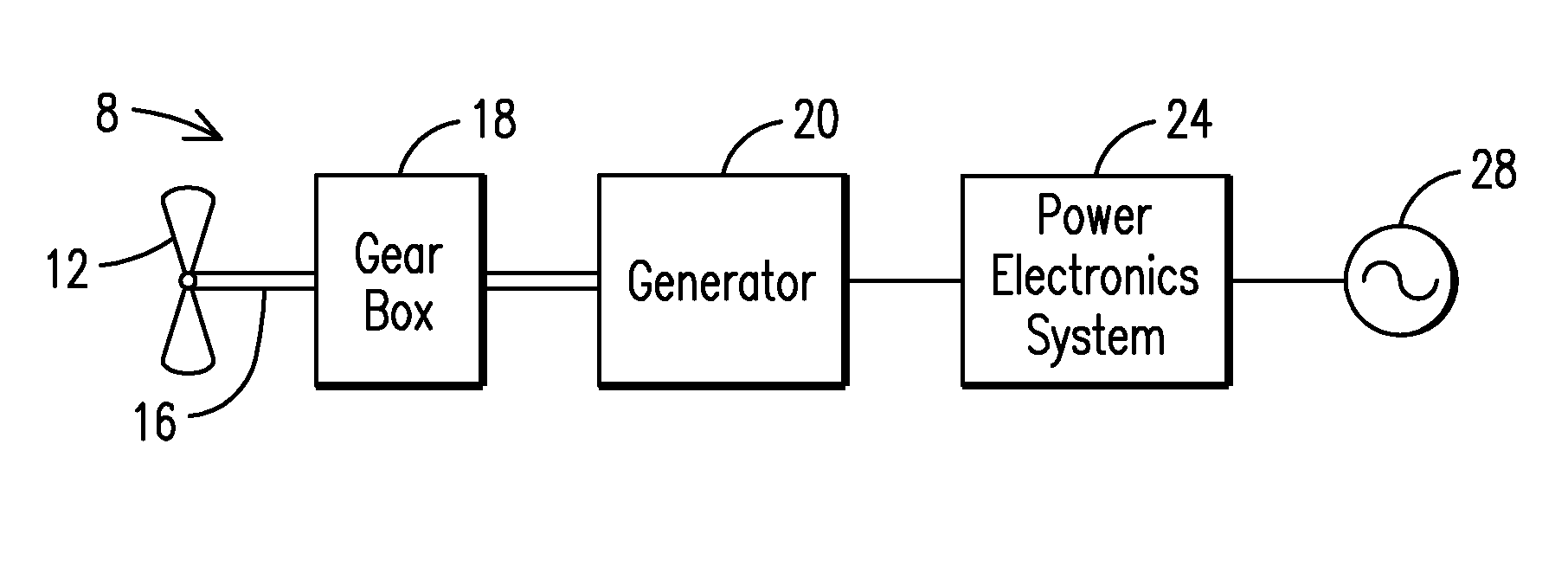
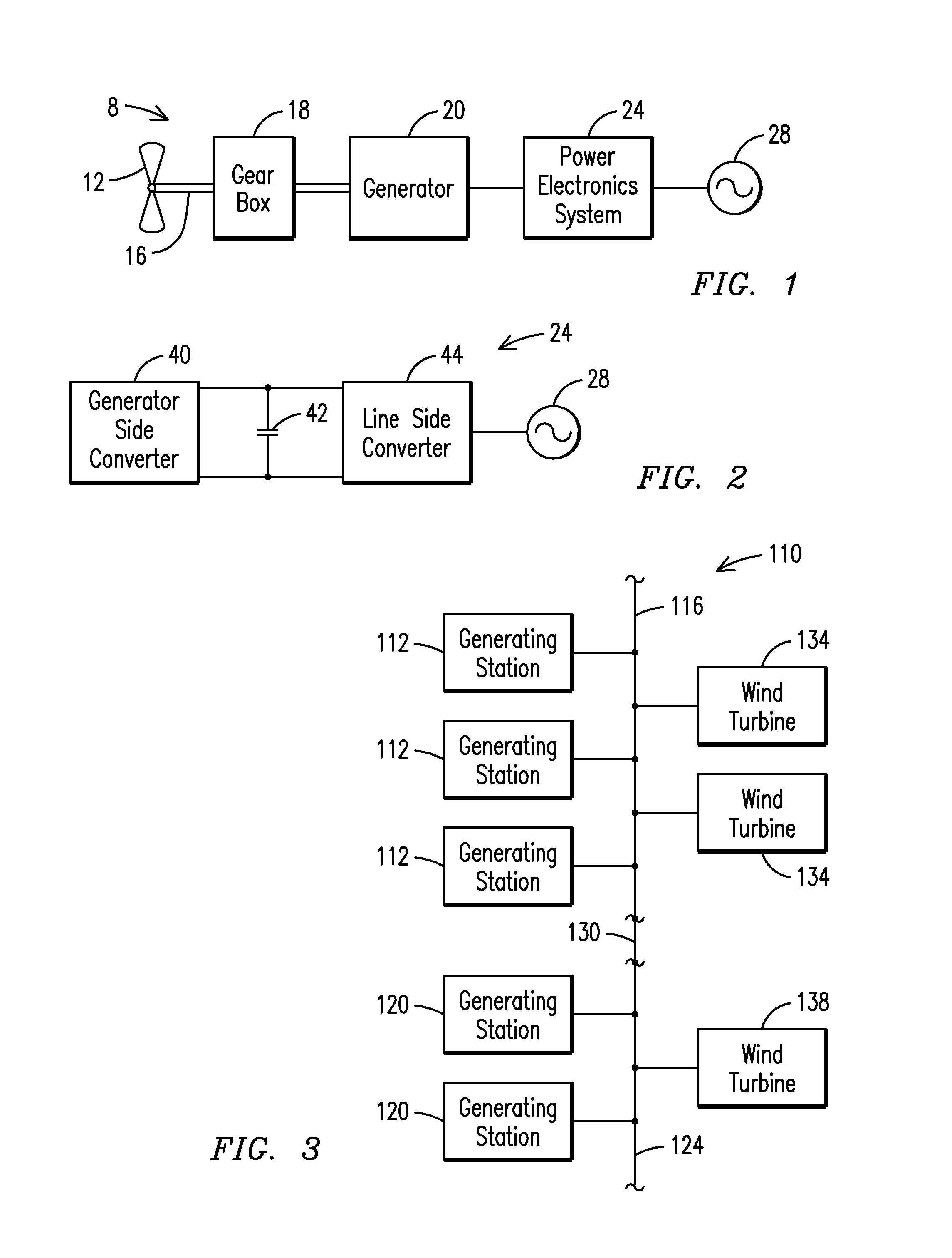
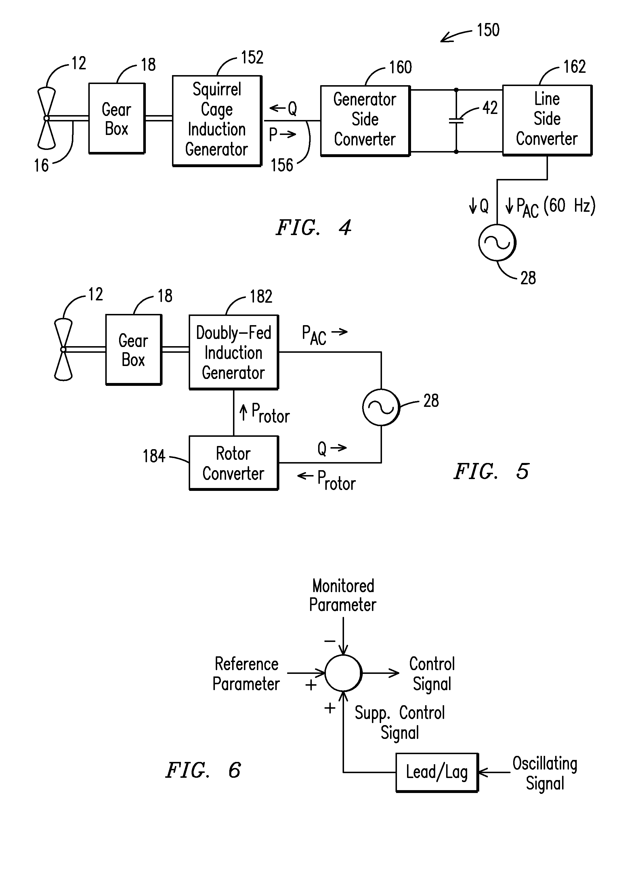
A wind turbine (8) for controlling power oscillations on a grid of a power system (28). The wind turbine (8) comprises rotor blades (12) for turning by the wind, an electric generator (20) rotatably coupled to the rotor blades (12), a power converter (24) responsive to electricity generated by the electric generator (20), the power converter (24) for converting the generated electricity to a frequency and voltage suitable for supply to the power grid (28), and the power converter for regulating voltage on the grid supplemented by modulating real power for damping the power oscillations.

Description

FIELD OF THE INVENTION[0001]The present invention relates generally to control of power systems and more specifically to power oscillation damping employing a full-conversion or partial conversion wind turbine or a doubly-fed induction generator wind turbine.BACKGROUND OF THE INVENTION[0002]In most cases, there is a phase angle difference between a sinusoidal current supplied to a power grid by an alternating current generator and a voltage at the generator's terminals. This phase angle difference between the voltage and the current is due to the nature of the load on the power grid. For a purely resistive load (i.e., having no energy storage properties) the voltage and current are in phase, i.e., the current and voltage reverse their polarity simultaneously and a direction of power remains fixed and does not reverse.[0003]For a purely reactive load the current and voltage are 90 degrees out of phase and the net power flow is zero as the power flows to and returns from the load due ...

Claims


Application Information

Patent Timeline
IPC IPC(8): H02P9/04
CPCH02J3/24H02J3/386H02P2101/15Y02E10/763H02P9/102H02J2300/28H02J3/381Y02E10/76H02J3/241H02J3/40Y02E10/72
Inventor NELSON, ROBERT J.
Owner SIEMENS GAMESA RENEWABLE ENERGY AS
Learn More