Controller for engine

Active Publication Date: 2011-05-12
DENSO CORP
View PDF2 Cites 32 Cited by
  • Summary
  • Abstract
  • Description
  • Claims
  • Application Information

AI Technical Summary

Benefits of technology

The present invention is made in view of the above matters, and it is an object of the present invention to provide a waste heat controller which is able to control engine waste heat quantity while restricting a deterioration in a fuel economy. Also, it is another object of the present invention to provide a heat-source controller which controls a heat-supply from

Problems solved by technology

Thus, it may excessively increase the fuel consumption and may cause a deterioration in fuel economy.
However, if the engine waste heat runs shortage, it is likely that enough heat quantity is not ensured for heating the interior of the vehicle.
However, the above Japanese patent does not show how much energy is used from wh

Method used


Image

  • Controller for engine
  • Controller for engine
  • Controller for engine

Examples


Embodiment Construction

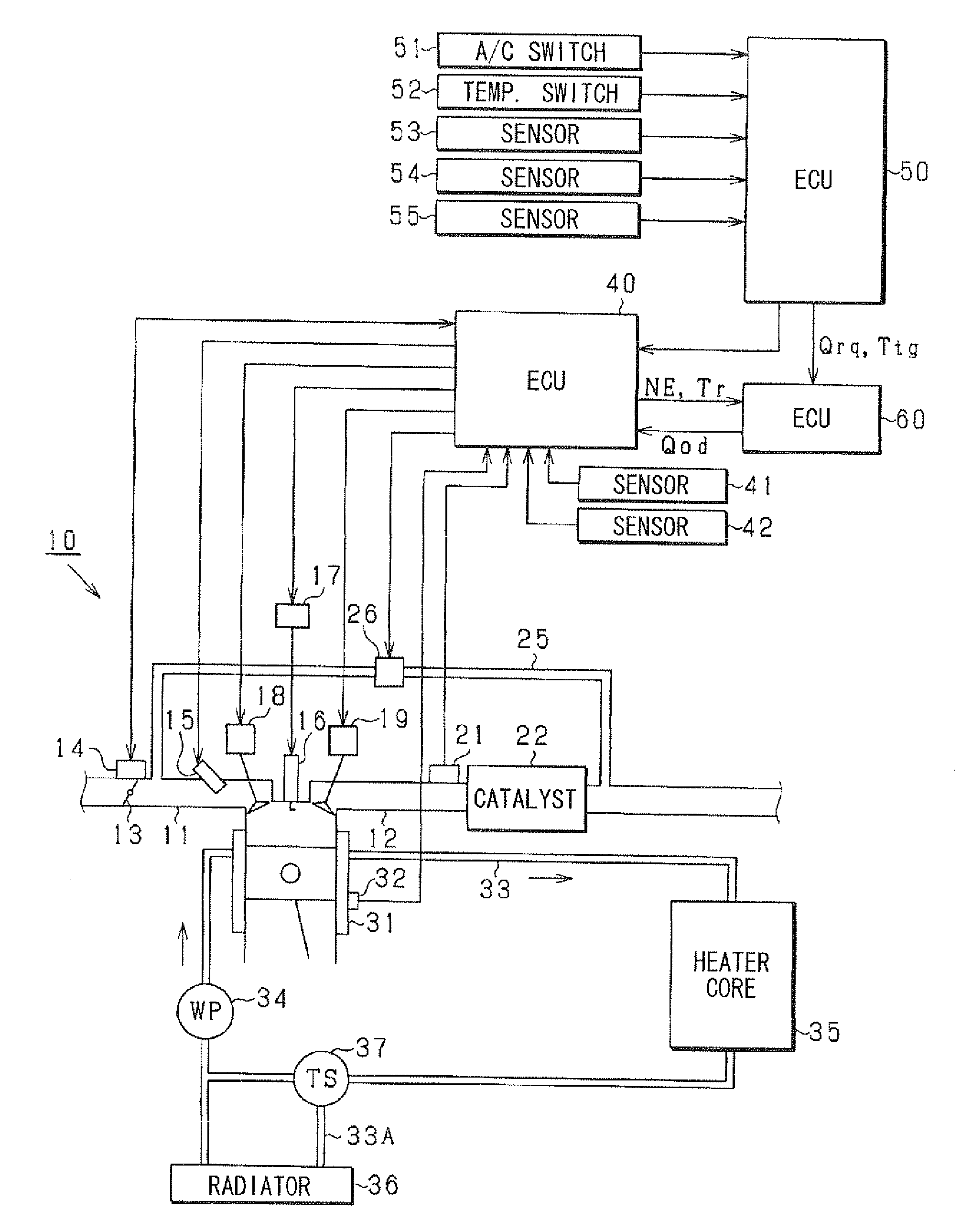
FIG. 1 is a schematic view of a waste heat control system (waste hear reuse system) according to an embodiment.

An engine 10 is provided with an intake pipe 11 and an exhaust pipe 12. A throttle valve 13 is provided in the intake pipe 11. The throttle valve 13 is driven by an electric throttle actuator 14, such as an electric motor. The throttle actuator 14 is provided with a throttle position sensor (not shown) which detects a throttle position.

The engine 10 is provided with a fuel injector 15, an igniter 17, a spark plug 16, an intake valve timing controller 18 and an exhaust valve timing controller 19.

The intake valve timing controller 18 advances or retards a valve timing of an intake valve, and the exhaust valve timing controller 19 advances or retards a valve timing of an exhaust valve.

An oxygen concentration sensor 21 detecting an oxygen concentration in exhaust gas is provided to the exhaust pipe 12. A three-way catalyst 22 which purifies the exhaust gas is provided downstrea...


PUM


Abstract

A waste heat controller controls waste heat quantity of an engine according to a required heat quantity along with a heat-utilize requirement. When the heat-utilize requirement is generated, a fuel-increase-rate indicating a fuel increase quantity is computed. A reference fuel-increase-rate is established to be compared with the fuel-increase-rate. Based on this comparison result, it is determined whether the waste heat increase control will be executed.

Description

CROSS-REFERENCE TO RELATED APPLICATIONThis application is based on Japanese Patent Applications No. 2009-259012 filed on Nov. 12, 2009, No. 2010-72922 filed on Mar. 26, 2010, and No. 2010-72923 filed on Mar. 26, 2010, the disclosures of which are incorporated herein by reference.FIELD OF THE INVENTIONThe present invention relates to controller for an internal combustion engine. Especially, the present invention relates to a waste heat controller which controls waste heat quantity of an engine in accordance with a heat-utilize requirement. Also, the present invention relates to a heat-source controller which controls a heat-supply from a heat source of a vehicle. Further, the present invention relates to an electric-power-source controller which controls an electric-power-supply from an electric-power source of a vehicle.BACKGROUND OF THE INVENTIONIn an internal combustion engine for a vehicle, the combustion energy includes kinetic energy and heat energy. This heat energy is utilize...

Claims


Application Information

Patent Timeline
IPC IPC(8): B60L1/00F02G5/00F27B9/36
CPCB60H1/00007B60H1/00428B60H1/00735F02D41/086Y02T10/166F02D2200/021F02D2200/0414F02G5/00Y02T10/44F02D41/40Y02T10/88Y02T10/12Y02T10/40
Inventor TANI, KEISUKE
Owner DENSO CORP
Why Eureka
Try Eureka