Imaging Spectrometer

a spectrometer and imaging technology, applied in the field of imaging systems, can solve the problem that the application of this prior spectroscopic sensor is limited to the ir rang

Inactive Publication Date: 2011-05-12
NATIONAL TSING HUA UNIVERSITY
View PDF4 Cites 13 Cited by
  • Summary
  • Abstract
  • Description
  • Claims
  • Application Information

AI Technical Summary

Benefits of technology

[0042]According to the present invention, preferably the real-time-image CCD sensor identifies high resolution line.

Problems solved by technology

The applications of this prior spectroscopic sensor are limited to the IR range.

Method used


Image

  • Imaging Spectrometer
  • Imaging Spectrometer
  • Imaging Spectrometer

Examples


example 1

Hyperspectral Imaging Optical System Design

[0060]The present invention proposed to construct a ground model of a hyperspectral imaging system (HSI) system. The ground model served the purposes of testing the optical and electrical functions and performances of such a system for the determination of the designing parameters in the future construction of a space born model. This HSI system was a precursor for a future space born HSI.

example 2

HSI System Architecture

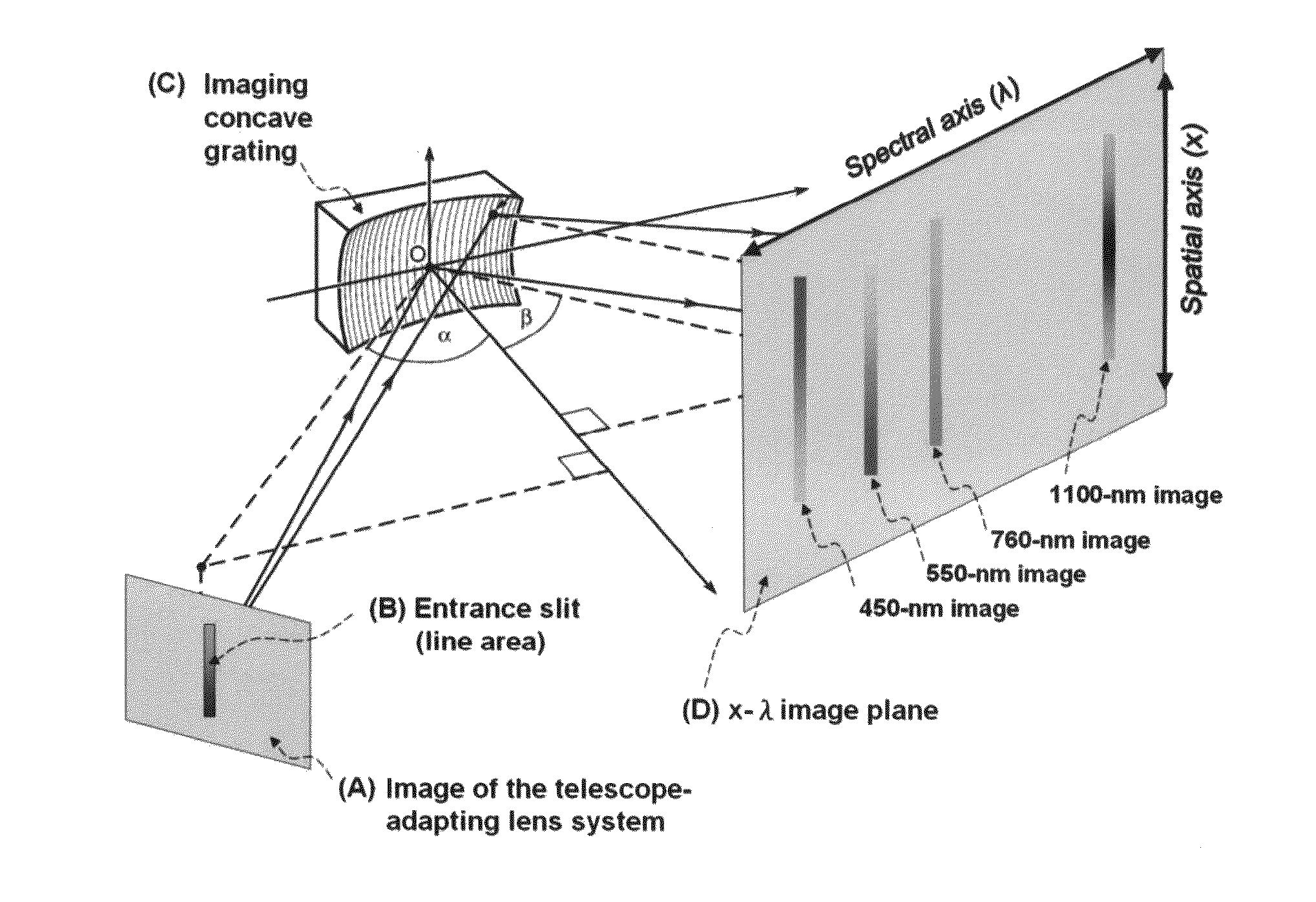
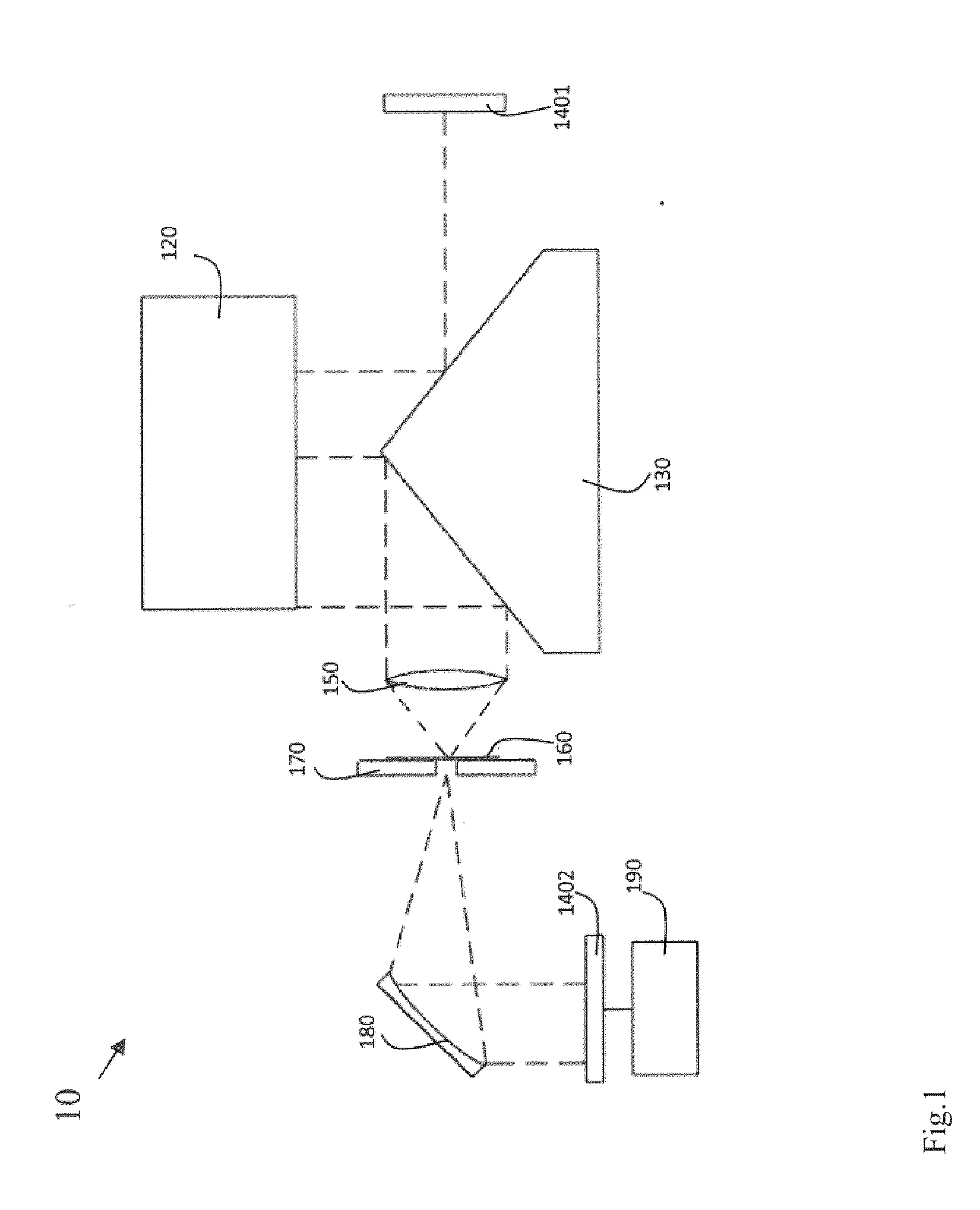
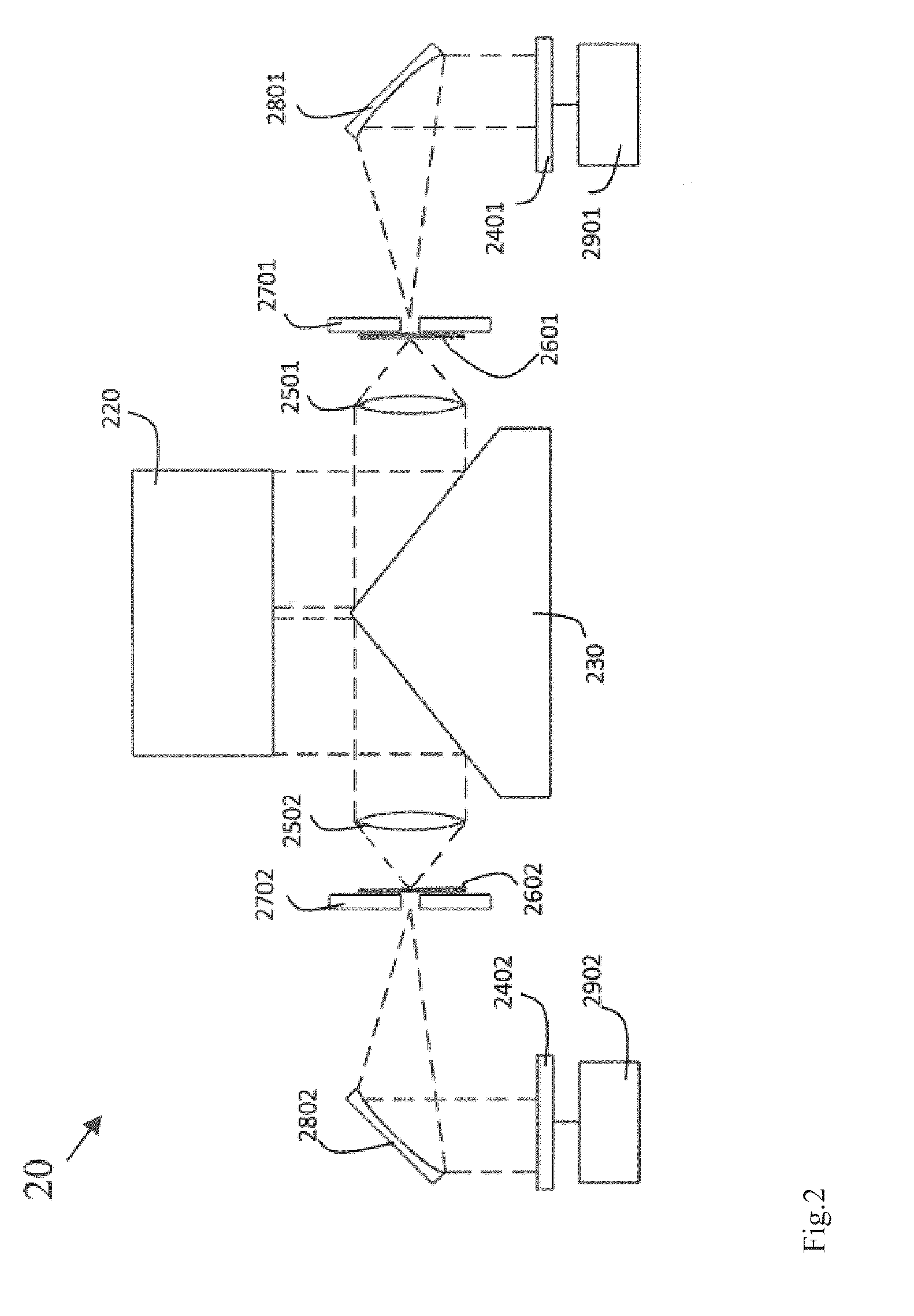
[0061]As shown in FIG. 4, the HSI system was consisting of three subsystems: (1) a RC type telescope system; (2) an adapting lens system and (3) an imaging concave grating (ICG) system. The telescope (A) formed an image on the image plane. In order to match the phase space of the telescope optical system to that of the ICG optical system, an adapting lens system (B) was incorporated in-between the optical output of the telescope (A) and input of the ICG system, i.e., the entrance slit (C). After the entrance slit (C), a flat mirror (D) re-directed the beam to an imaging concave grating (E). The image concave grating generated hyperspectral images on the CCD detector (F).

example 3

Principle of Wavelength Dispersion

[0062]FIG. 5 illustrated the physical principle of wavelength dispersion. In the ICG system, the wavelength dispersion was performed by a diffraction grating according to the grating equation, which described the relationship between the dispersed wavelength λ, and the diffracted angle β of λ:

(sinα+sinβ)=mλd0Eq.4.3-(01)

wherein α was the incident angle, m was the diffraction order and d0 was the pitch of the diffraction grating.

[0063]With a fixed incident angle α and diffraction order m, light wave of different wavelengths were diffracted to different exit direction β according to its wavelength. λ as the following:

β=sin-1(mλd0-sinα)Eq.4.3-(02)


PUM


Abstract

The present invention relates to an imaging device simultaneous records image and spectrum of an interested target utilizes spectral technology to acquire, process and exploit image data or spectrum data. The present invention allows for real time detection and identification of not only the traditional images but also the spectrum which shows the surface of the earth or reveals the chemical composition of the targeted tissue. The present invention includes a reflecting telescope, an imaging concave grating (ICG) system with spectrometer and a processor that performs spectral analysis on spectral data generated from the spectrometer.

Description

FIELD OF THE INVENTION[0001]This invention relates to an imaging system for simultaneous recording of image and spectrum data of an image from a target.BACKGROUND OF THE INVENTION[0002]Various imaging systems and techniques have been used for biological, medical, and aerospace applications. One approach involves multispectral imaging with an array detector. The array can be a charge-coupled device (CCD) or a photo-diode array.[0003]A spectrometer is typically implemented to measure photometry with regard to radiation sources, and a grating in such spectrometer is a component for wavelength dispersing.[0004]U.S. Pat. No. 5,550,375 provides an infrared spectroscopic sensor for gases, which consisted of a micro-structured spectrophotometer, a multi-frequency IR radiation source, and an IR radiation receiver. In many cases, the absorption occurs in much broader wavelength, from UV / Visible to near infrared (NIR), and even the far IR range. The applications of this prior spectroscopic sen...

Claims


Application Information

Patent Timeline
Patent Type & Authority Applications(United States)
IPC IPC(8): G01J3/40
CPCG01J3/02G01J3/0208G01J3/36G01J3/0291G01J3/2823G01J3/021
Inventor LEE, KUAN-RONGKO, CHENG-HAO
Owner NATIONAL TSING HUA UNIVERSITY
Why Eureka
Try Eureka